Metal Foil Resistors, calibration method. Measurement systems. Kelvin method. 2
The calibration method.Charly García
Joseph Szware's calibration method. Measurement systems. Kelvin method.
This document is related to the document "Metal Foil Resistors ", https://telegra.ph/Metal-Foil-Resistors-1-07-15
The calibration method was developed by Joseph Szware,
Joseph Szware,Resistive Electrical Component, United States Patent 4,378,549 ,1983
This method is based on the calibration method of Tellkamp Bernhard US 2953764 A, 1958, his system is represented below by means of his drawing.

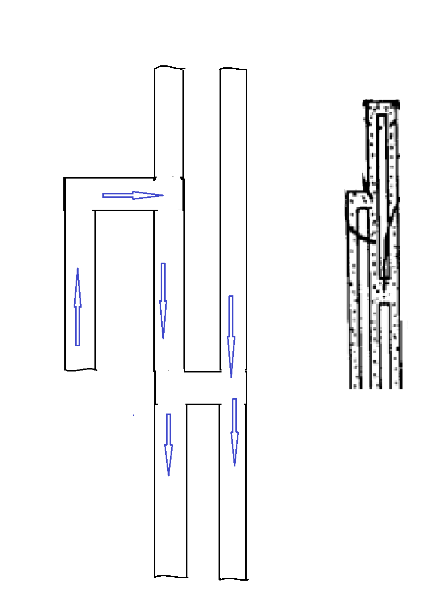
In the Tellkamp Bernhard method, a metal film of a nickel-chromium alloy is deposited on a glass substrate, by means of the evaporation of this alloy in a vacuum chamber as described below.
The metal film 3 (see Tellkamp drawing) is preferably a metallic deposit suitable for precision resistors, such as a nickel-chromium alloy deposit. The metallic film 3 can be deposited using a method of vapor deposition of the alloy on the glass substrate 2, in a vacuum enclosure at vaporization temperatures, as shown in the following drawing.

The base 2 is placed within the enclosure at a position in the path of the vaporized metal particles, and when the particles strike the base 2, through a mask, the film is developed to the desired thickness. To obtain a pattern (the lines that form the resistor) on the film 3, as shown in the illustration, the base 2 is first coated using a photoligraphy method with the mask. The result obtained is like the one shown in the following drawing.

The point indicated by 9, which is at the ends of the resistor, are used for connection to the copper terminals of the resistor. The point 2 is the glass substrate where the metallic film is deposited. The point 3, are the metallic lines that follow the drawing of the resistor pattern. The points 10, 14, 15, 17, 18 and 22 are jumpers that will be cut during resistance calibration.
Suppose we concentrate, for the explanation of the calibration method, on the point 10, which forms an equivalent circuit as shown.

Before the cut of the bridge Rp1, the partial resistance is Rt1, after the cut the partial resistance is Rt2, where Rt2>Rt1, with which the total resistance between A and B (see drawing above) increases a certain percentage referred to the initial resistance before calibration.

In the previous frame drawing with red lines, an area of the chip to study what happens, when the resistor is calibrated, with this area enlarged as shown below.

This area has a deviation, whose effect during calibration, if it is cut, is to increase the resistance value of the entire resistor. The calibration is done in the following way, an operator or a machine, proceeds to measure the total value of the resistor, this is compared with the desired value and according to a table made for this resistor, the area to be cut can be cut or not delete, it may be that it is not necessary to cut this zone and move on to the next zone and so on until the calibration is finished.

The calibration method developed by Joseph Szware.
Joseph Szware,Resistive Electrical Component, United States Patent 4,378,549 ,1983
https://telegra.ph/Metal-Foil-Resistors-2-08-07
Szware divided the resistance as shown in the following drawing, what is the pattern drawing of the resistor,

Szware divided the resistance as shown in the following drawing
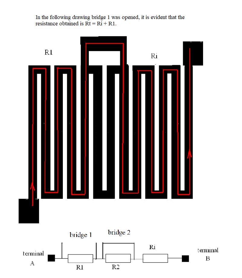
The principle of Joseph Szware is as follows, in his drawing we see that in the calibration area at the top there are percentages indicated: 19.6%, 12.1%, 7.5%..., which are related to the initial resistance of the resistor, that is, with all the bridges connected, as these bridges open, the total resistance Rt increases, measured between its terminals, the operator or the machine after the first cut, calculates which bridge to open next, During this operation, avoid exceeding the desired value to be obtained. It may happen that if the engineering did not correctly design the drawing of the resistor, the master, when a percentage value is opened, the desired value is exceeded.
By way of simplification, the calibration system is described with the following drawing, with Ri, which is the resistance measured between A and B, before calibration, este valor Ri sera tomado como referencia y todos los porcentajes (19.6%, 12.1%, 7.5%...) estan relacionados a este valor.

In the following drawing, the bridge of R1 was cut and it turns out,
Measurement systems. Kelvin method
The four-point measurement method, also known as the Kelvin method, is an electrical impedance measurement technique that uses a voltmeter and ammeter to achieve more accurate resistance measurements than using the traditional two-point measurement technique.
Accuracy problems in two-point measurements.
Two-pronged resistance measurement. The ohmmeter measures resistances wired in series with the unknown resistance R.
The most common method of resistance measurement is the two-prong method, using a multimeter or ohmmeter to measure the desired resistance. However, the resistance measured by the instrument is the sum of the wiring resistances, Rcable and Rcable' and the unknown resistance. When dealing with large resistors compared to wired resistors, this deviation is small, so the measured value will be close to the resistor value. On the other hand, for resistances comparable to lead and contact resistances, the measured value will be far from the resistance value, so this method loses accuracy.
Also, when dealing with small resistances, the effects of contact potentials that may be present from connecting two dissimilar metals must be taken into account. These potentials can vary both with the temperature difference between the metals and with the polarity of the source.1

The four-poitn measurement method is particularly useful for small resistance measurements, as it eliminates the contributions of wiring resistances and contact potentials on the final resistance measurement in question; this is why some high precision ohmmeters are built using similar circuitry.
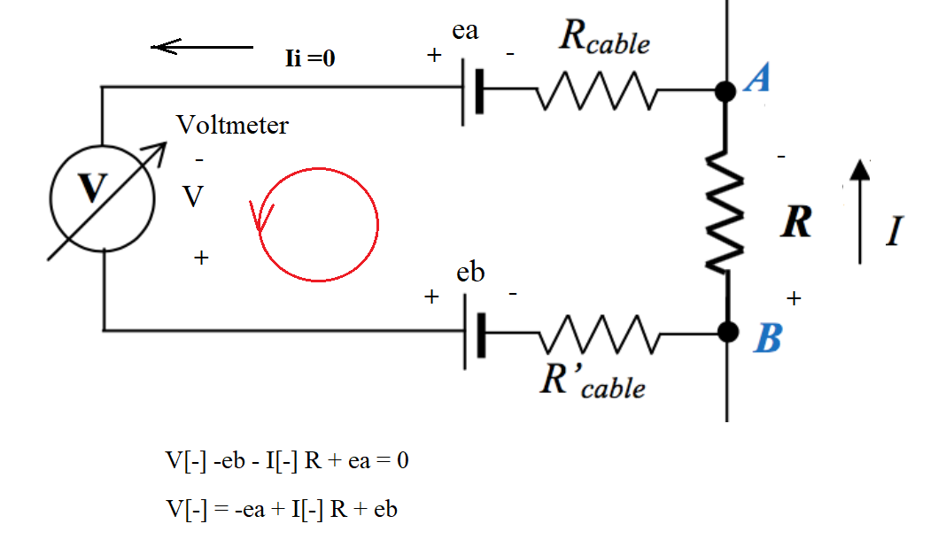
The four-point measurement method makes use of two linked circuits fed by a direct current source: one through which current circulates from the source measured with an ammeter, external circuit in the schematic, and another in parallel to the unknown resistance. , containing a voltmeter, circuit inside on the schematic.. In addition, the resistance of the cables joining the circuits is low, so the voltage drop over them is negligible. So, we have a measurement:

The four-point measurement method makes use of two linked circuits powered by a direct current source: one through which current flows from the source measured with an ammeter (external circuit in the schematic), and another in parallel to the resistance unknown, which contains a voltmeter (inner circuit in the schematic). As voltmeters have a very large internal resistance (usually around 10 MΩ), practically no current flows through the internal circuit. In addition, the resistance of the cables joining the circuits is low, so the voltage drop over them is negligible. So, we have a measurement:
Kirchhoff'' voltage law :
V[+]= ea + I[+] R - eb
where ea and eb represent the contact potentials, and [+] indicates the polarity of the source in this first current and voltage measurement. If we invert the polarity of the source, identifying the current and voltage measured in this case [–], we then measure
V[-] = -ea + I[-] R + eb
Adding the two expressions, we get
V[+] + V[-] = ( I[-] + I[-] ) R
R = ( V[+] V[-] ) / ( I[+] + I[-] )
In this way, the four-pin measurement method allows small resistances to be measured, since it eliminates the contribution of wiring resistances in the measurement and contact potentials. In addition, it is convenient to use a source that regulates the power supply current of the circuit, maintaining a given voltage between its ends, and setting a limit for the current supplied. This will allow limiting the power dissipated by the circuit to the limits allowed by the instruments and elements. using the maximum supply current y Rext, and at the same time work with a constant voltage on the circuit, in another chapter we will see the use of a bridge system : the Kelvin bridge, a Kelvin bridge, also called a double Kelvin bridge and in some countries a Thomson bridge, is a measuring instrument used to measure unknown electrical resistances less than 1 ohm. It is specifically designed to measure resistors constructed as four terminal resistors.
Metal Foil Resistors. Kelvin bridge. 3
https://telegra.ph/Metal-Foil-Resistors-Kelvin-bridge-3-08-10