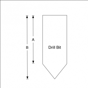
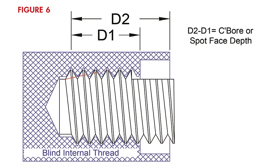
Hole Depth

👉🏻👉🏻👉🏻 ALL INFORMATION CLICK HERE 👈🏻👈🏻👈🏻
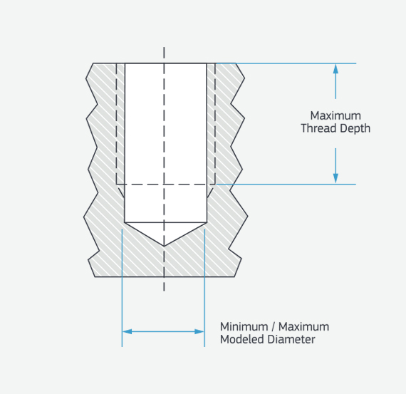
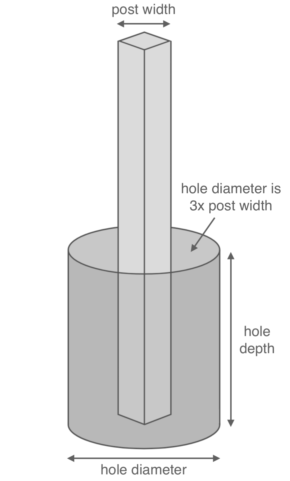
Hole depth should be slightly longer than the screw length, to allow for chip accumulation.
The hole depth is determined by the nozzle diameter and nozzle pressure drop irrespective of a casing or open hole well. The greater the nozzle diameter, the higher the nozzle pressure drop, and the stronger the breaking ability of the water jet, the greater the depth of perforation.
In this chapter, we compare and analyze the characteristics of the pressurization for three hole depths of 550, 600, and 700 mm. Fig. 3.23 shows the wall pressure distribution for different hole depths. The three wall pressure curves almost coincide; so long as the depth of the hole is greater than the length of the jet attenuation, the pressurization inside the hole is the same regardless of the hole depth.
Figure 3.23. Effect of the hole depth on the wall pressure.
However, a deep perforation hole can reduce the formation fracture pressure; hence as far as possible a deep perforation hole must be obtained during the perforation, which is more conducive to crack formation and the extension of fracture.
URL: https://www.sciencedirect.com/science/article/pii/B9780128128077000030
Manhours are for all labor involved in the above types of excavation under average conditions and in accordance with the following typical crews.
Typical Hand Digging Crew–Foreman, truck driver, and 4 workers.
Typical Power Digger Crew–Foreman, truck driver, and 2 workers.
Manhours are for maximum hole diameter of 2′0″.
Manhours do not include equipment usage.
If hole locations are hard to get to and work area is small and limited, add for these factors.
URL: https://www.sciencedirect.com/science/article/pii/B9780884152286501659
Etsuko Ishikawa, ... Youichi Akasaka, in Optically Amplified WDM Networks, 2011
The main and second hole depths decreased as the wavelength of saturation signal became longer. These characteristics of the main and second hole depths can be explained by the energy structure model as shown in Figure 5.21. The solid bars show the region over the Stark manifolds that can contribute to the formation of the second hole. The dashed bars show those that can contribute to the formation of the main hole. In addition, the length of solid bars and that of dashed bars correspond to the energy of the second and main hole, respectively. The population of the half-toned Stark manifolds can be depopulated by a saturating signal. Figure 5.21(a) and 5.21(b) show the burned areas by the saturating signal whose wavelength is longer and shorter, respectively. As shown in Figure 5.21, the population of the Stark manifolds within the 4I13/2 state decreases when the wavelength of saturating signal becomes longer . Therefore, one reason for the decrease of the second and main hole depth is considered to be due to the decrease of the population of the Stark manifolds within the 4I13/2 state.
FIGURE 5.21. Depopulated energy state region of the Er3+ ion energy structure by the saturating signals. ((a) shorter wavelength, (b) longer wavelength).
URL: https://www.sciencedirect.com/science/article/pii/B9780123749659100056
A piezometer was installed in a 8 m depth hole to measure pore pressure and ground water level. Initially, the PVC casing was installed in the borehole. Then the piezometer was inserted into casing and grounded in the borehole. It was covered with a cotton bag filled with sand and then the bag was tightened with a lilon thread. A sand intake zone was formed around the piezometer and a bentonite seal was placed above the sand zone surrounding the sensor. The entire borehole was filled with a bentonite cement grout. Finally, all the sensors' input ports were connected with power supply and output was connected to WN for transmitting the sensors' data to the server.
URL: https://www.sciencedirect.com/science/article/pii/B9780128031940000015
Boyun Guo Ph.D, Gefei Liu, in Applied Drilling Circulation Systems, 2011
The selected mud pump should also be capable of providing pressure that is strong enough to overcome the total pressure loss and pressure drop at the bit in the circulating system at the total hole depth. The pressure loss depends on the mud properties, the drill string configuration, the borehole geometry, and the mud flow rate. The pressure drop at the bit should be optimized based on the total pressure loss in the system to maximize bit hydraulics. Therefore, extreme borehole architecture and condition should be considered.
Maximum pressure loss normally occurs when the total hole depth is reached. At this point, the drill string and the open hole section assume their longest values. The borehole configuration is shown in Figure 3.3. To perform pressure loss calculations, it is convenient to put the dimension (lengths and diameters) data along the circulating path in the graph.
Figure 3.3. Borehole configuration at the total depth.
The maximum circulating pressure normally occurs at the total depth with extreme borehole conditions. These conditions include the use of a mud flow rate higher than normal to clean the hole. Different mud properties are used, and the mud weight is increased before tripping out the drill string. These extreme parameter values should be marked in the borehole configuration graph for pressure loss calculations.
The maximum expected circulating pressure is the total frictional pressure loss and pressure drop at the bit at the total hole depth. The frictional pressure loss depends on the fluid properties, the flow velocity, the flow regime, and the length of the flow path. Under normal drilling conditions, turbulent flow exists inside the surface equipment, the drill pipe, the drill collar, and the annulus outside the drill collar. Laminar flow normally exists in the annulus outside the drill pipe. The pressure loss in turbulent flow is usually higher than that in laminar flow. For the purpose of pump selection, assuming turbulent flow throughout the circulating system will result in conservative values of pressure losses.
This section presents the analytical method used for predicting the pressure losses in the drill string and in the annulus, as well as considerations for pressure drop at the bit. The length of the surface equipment is considered to be a small fraction of that of the drill string. Necessary hydraulics models were presented in Chapter 2. For directional and horizontal drilling, the pressure losses through the MWD and LWD tools are considered to be negligible. The pressure drop at the mud motor is considered as a specific value between 200 psi and 600 psi, depending on motor size.
However, the pressure drop at the bit is not calculated with Eq. (2.64) in the process of pump selection. For the optimum bit hydraulics, the pressure drop at the bit should be selected based on the total pressure loss in the system. According to the maximum bit hydraulic horsepower criterion (see Chapter 4), the following relation should be held:
where pp is the pump pressure in psi or Pa, and m is the flow rate exponent. If the Blasius correlation is used for friction factor determination, Eq. (3.2) shows m = 1.75. However, according to the maximum jet impact force criterion (see Chapter 4), the following relation should be held:
The minimum required pump pressure is expressed as
Combining Eqs. (3.1) and (3.3), the following relation is derived for the maximum bit hydraulic horsepower criterion:
Combining Eqs. (3.2) and (3.3), the following relation is derived for the maximum jet impact force criterion:
From which the expressions for the required pump pressure are
for the maximum bit hydraulic horsepower criterion and the maximum jet impact force criterion, respectively.
For the data in Illustrative Example 3.1 and the additional data given in Figure 3.4, determine the minimum required pump pressure. Assume the maximum mud weight of 12 ppg (1,440 kg/m3), the maximum plastic viscosity of 15 cp (0.015 Pa-s), the maximum yield point of 10 lb/100 ft2 (4.78 Pa), pipe wall roughness of 0.00025 in. (0.00635 mm), pressure drop at the mud motor of 200 psi (1,379 kPa), and a mud flow rate of 300 gpm (1.14 m3/min).
Figure 3.4. Example of borehole configuration at the total depth.
This problem is solved using the spreadsheet program Pump Pressure.xls that is attached to this book. To calculate the required pump pressure using Table 3.4, (1) select a unit system, (2) update the data in the Input Data column, and (3) click on the Solution button and obtain the result. The result is summarized in Table 3.5 for the maximum bit hydraulic horsepower criterion. It indicates that the required pressure is 3,461 psi (23.86 MPa).
Table 3.4. Part of the spreadsheet program Pump Pressure.xls
Table 3.5. Summary of Calculated Pressures
URL: https://www.sciencedirect.com/science/article/pii/B9780123819574000036
Parameterization of the torque tube holes is shown in Figure 5.50. Hole depth and half of the hole length are selected as design variables. When the length of the holes is changed, the holes either expand or contract symmetrically. Also, the position of the hole is maintained such that it always remains centered between the adjacent fins. From initial tests, it was observed that the maximum stress occurs near the middle bracket. Hence, except for the two holes adjacent to the middle bracket, the design variables of all other holes are grouped together; implying that width and length of the Holes 1, 2, 5, 6, and 7 are changed at the same amounts, respectively. This reduces the number of design variables from 14 (2 design variables per hole time 7 holes) to 6.
FIGURE 5.50. Parameterization of torque tube holes.
URL: https://www.sciencedirect.com/science/article/pii/B9780123985125000050
A.R. Ghasemi, ... M.M. Shokrieh, in Residual Stresses in Composite Materials, 2014
Calibration factor matrices of quasi-isotropic laminates [0/± 45/90]S, obtained from drilling half of the thickness of the laminate, are presented in Table 4.12. Although each separate layer and total quasi-isotropic laminated were orthotropic, calibration factors terms, C12 and C32, in none of the matrices were zero. Calibration factors terms, C12 and C32, are the effect of the shear residual stresses on the measured strains along the 0- and 90-degree strain gages. Therefore, during drilling of the first layer, the effect of adjacent layers in a 45-degree direction has prevented the terms C12 and C32 from becoming zero. By increasing the hole depth, the effect of released strains in depth reduced on the surface. Therefore, by increasing the depth, and values of indices n = m, numerical values of the calibration factor matrices have been reduced.
Table 4.12. Calibration factors of symmetrical quasi-isotropic [0/± 45/90]s
When n ≠ m, the calibration factors matrix represents the released strains, due to the geometry change of the hole during drilling. Whenever the differences between m and n increases, the change of the numerical values of calibration factors are decreased, which means decreasing the effects of the upper layers with further distance on the released strains of the lower layers.
Comparison between data provided in Tables 4.10 to 4.12 revealed two majors points:
By increasing the hole depth, measured strains on the surface in comparison to the released strains in the depth will be rapidly reduced, which is illustrated by decreasing numerical values of the calibration factors matrices. This phenomenon indicates that there must be a limitation on the depth of the hole. According to Saint–Venant principles, the hole depth cannot be more than the hole diameter.
By increasing the hole depth, the effect of upper plies with further distance on the released strain of the lower plies due to the drilling of the lower plies would be decreased. Therefore we may conclude that increase in released strains of the lower plies due to the depth increase is more related to the released strains of the upper adjacent plies. This finding is important and simplifies the integration method in layered composites.
As it was explained in the previous section, increasing the number of hole-drilling increments will rapidly increase the number of calibration factor matrices. Usually the number of calibration factor matrices is the same as the number of hole-drilling increments. For instance, in the fourth and eighth increments of a hole-drilling process, the numbers of calibration factor matrices are 4 and 8, respectively.
This section has proved that the residual stresses of each ply has an effect on the released strain of ply underneath during the hole-drilling process and its effect on the released strain of the other plies is negligible. Therefore, calibration factor matrices of each hole-drilling step are summarized in two matrices. The first matrix results from releasing residual stresses due to hole drilling of each orthotropic ply. The second matrix is due to the increase of the hole depth and expresses the effect of the residual stress of an upper given ply on the released strain of its underlying ply. With this result, in each row of the lower triangular matrix (Cij)mn, only two matrices have been changed, and other calibration factor matrices remain constant.
URL: https://www.sciencedirect.com/science/article/pii/B9780857092700500043
Minimizing waste disposal costs starts with the drilling program. The most important factors in planning the drilling operation are
Hole size and depth—minimize solids generated
Mud type—inhibitive water-based, NADF
Solids control equipment—dewatering/zero discharge systems
Of equal importance while drilling and after well completion is a plan to handle and dispose of the cuttings and excess fluids, both drilling and completion, generated. The following is from API Recommended Practice 51R (API, 2009), which is free from the API website (www.API.org).
Completion fluid selection should take into account the safety and logistics of transporting, handling, storing, and disposing of clean and contaminated fluid. For both new and existing well sites, all fuels, treatment chemicals, completion brines, and other similar liquids should be properly stored in labeled containers intended for that purpose. Containment should be constructed so spilled fuels or chemicals do not reach the ground.
Wherever practical, tanks or existing drilling pits should be used for completion and workover operations. Completion brines and other potential pollutants should be kept in lined pits, steel pits, or storage tanks. If a new earthen pit is necessary, it should be constructed in a manner that prevents contamination of soils, surface water, and groundwater, both during the construction process and during the life of the pit. Consideration should be given to the use of tanks or lined pits to protect soil and groundwater, especially for brines and oil-based fluids.
Normal operations should preclude oil in pits. However, in the event that well completion operations dictate use of pits containing oil for a brief period of time, they should be fenced, screened, netted and/or flagged, as appropriate, to protect livestock, wild game, and fowl. Refer to the Migratory Bird Treaty and Enforcement Improvement Act for additional guidance. Oil accumulated in pits should be promptly removed and recovered, recycled, or disposed.
All liquids and other materials placed in pits should be recovered, recycled, or disposed in an environmentally acceptable manner (determined by the constituents in the material and the environmental sensitivity of the location). When operations are completed, pits not required for well operation should be closed in accordance with the environmental sensitivity of the location. The surface area should be restored to a condition compatible with the uses of the adjacent land area. Any pit retained should be of minimum size commensurate with well operations. Refer to API Environmental Guidance Document: Onshore Solid Waste Management in Exploration and Production Operations for additional information and permitting requirements.
URL: https://www.sciencedirect.com/science/article/pii/B9780128047514000146
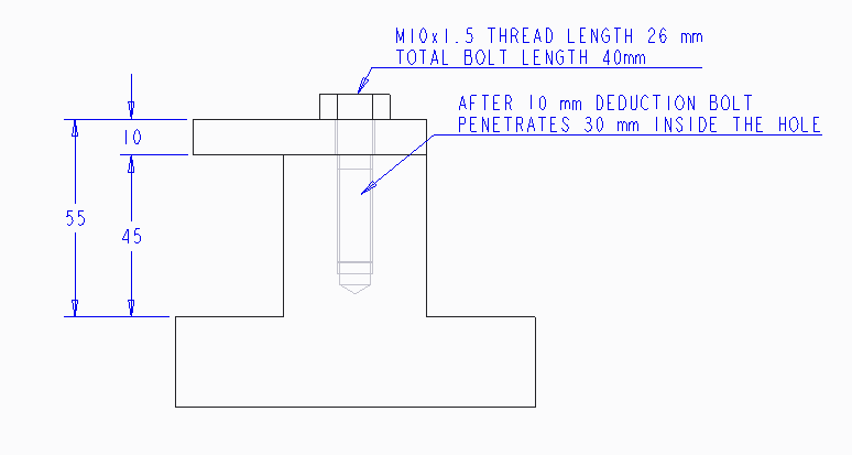
Thread-cutting screws have a sharp cutting edge removing material as it is inserted. It is therefore important for the hole depth to be slightly longer than the screw, so that the removed material is deposited from the device and does not become trapped internally. This type of screw reduces the creation of internal stresses and is therefore more suitable for higher stiffness materials, that is with a flexural modulus between 1380 MPa (200,000 psi) and 6900 MPa (1,000,000 psi).
For fiber-reinforced plastics, thread-cutting screws give excellent performance due to high thread engagement, high clamp loads, and minimal residual stresses, which can all generate failure following insertion of the fastener. For brittle plastics, that is, with a flexural modulus above 6900 MPa (1,000,000 psi), during insertion of the thread-cutting screw, granulation can take place leading to the entrapment of debris between the screw threads, leading to pull-out at lower predicted force values. To overcome this problem, screws with finer threads are recommended for fastening these types of material. If repeated reassembly of brittle plastics is required, then it is recommended that a metal insert is used, as the hole would otherwise become too big to reuse the same screw type.
Only a minimal number of reassemblies can be carried out with thread-cutting screws as the thread can become stripped. If removal and reassemblies are necessary, then a Type-T screw should be used initially and then replaced with a standard screw. This type of self-tapping screw provides acceptable performance in solid wall parts, but is not recommended for structural foam [1, 5, 7, 11].
URL: https://www.sciencedirect.com/science/article/pii/B9780815515814500202
We use cookies to help provide and enhance our service and tailor content and ads. By continuing you agree to the use of cookies.
Copyright © 2021 Elsevier B.V. or its licensors or contributors. ScienceDirect ® is a registered trademark of Elsevier B.V.
ScienceDirect ® is a registered trademark of Elsevier B.V.
Creo Parametric•5,5 тыс. просмотров
Mark Lindsay CNC•10 тыс. просмотров
4K Side - Creo Tutorials•65 тыс. просмотров
CAD CAM Tutorials•40 тыс. просмотров
howENGINEERSdoit!•129 тыс. просмотров
Nikita & Alyssa Sergiyenko•29 тыс. просмотров
Jamie French Porno
Stream Free Online Porn Hd
Multi Hole
Ftv Skinny Girls Video Hd
Guy Best Porn
Hole Depth - an overview | ScienceDirect Topics
Driller's depth - Wikipedia
Kola Superdeep Borehole - Wikipedia
Tree Planting Depth for New Trees | Proper Hole Depth & Wi…
Depth in a well - Wikipedia
Hole Depth