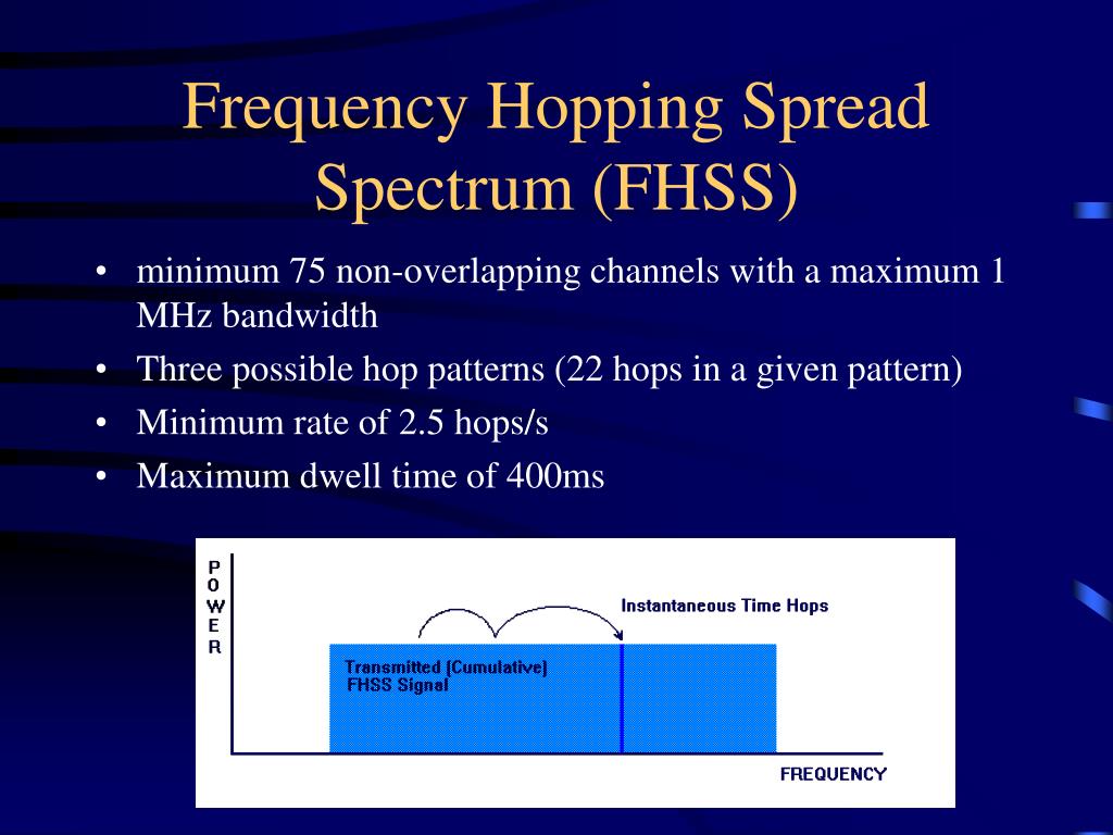
Frequency Hopping Spread Spectrum

🛑 👉🏻👉🏻👉🏻 INFORMATION AVAILABLE CLICK HERE👈🏻👈🏻👈🏻
"FHSS" redirects here. For other uses, see FHSS (disambiguation).
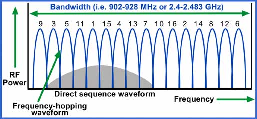
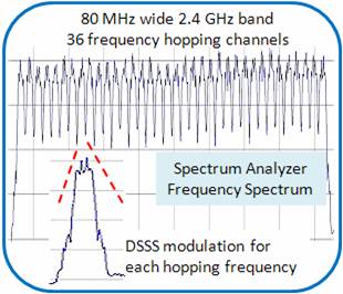
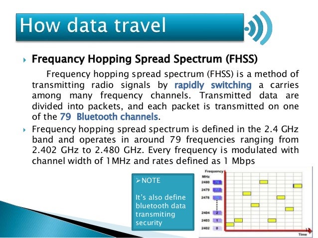
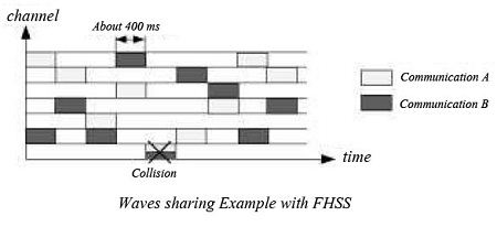
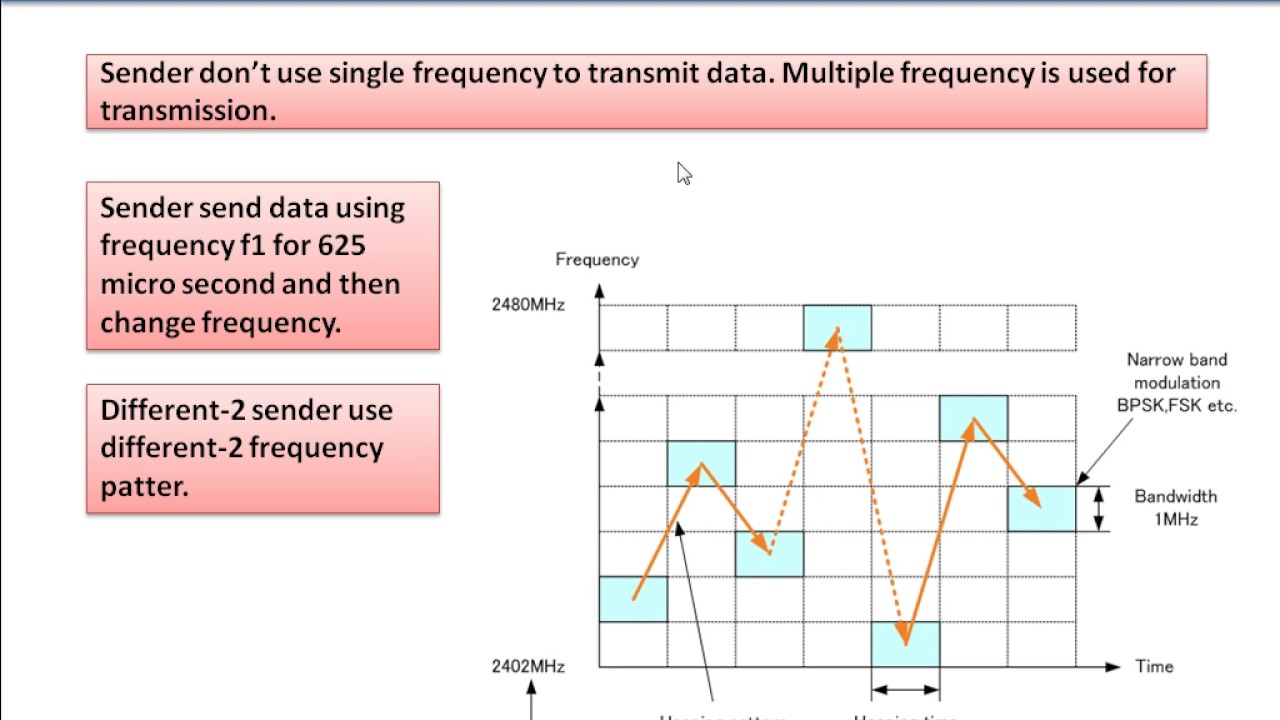
Frequency-hopping spread spectrum (FHSS) is a method of transmitting radio signals by rapidly changing the carrier frequency among many distinct frequencies occupying a large spectral band. The changes are controlled by a code known to both transmitter and receiver. FHSS is used to avoid interference, to prevent eavesdropping, and to enable code-division multiple access (CDMA) communications.
The available frequency band is divided into smaller sub-bands. Signals rapidly change ("hop") their carrier frequencies among the center frequencies of these sub-bands in a predetermined order. Interference at a specific frequency will only affect the signal during a short interval.[1]
FHSS offers three main advantages over a fixed-frequency transmission:
Spread-spectrum signals are highly resistant to deliberate jamming, unless the adversary has knowledge of the frequency-hopping pattern. Military radios generate the frequency-hopping pattern under the control of a secret Transmission Security Key (TRANSEC) that the sender and receiver share in advance. This key is generated by devices such as the KY-57 Speech Security Equipment. United States military radios that use frequency hopping include the JTIDS/MIDS family, the HAVE QUICK Aeronautical Mobile communications system, and the SINCGARS Combat Net Radio, Link-16.
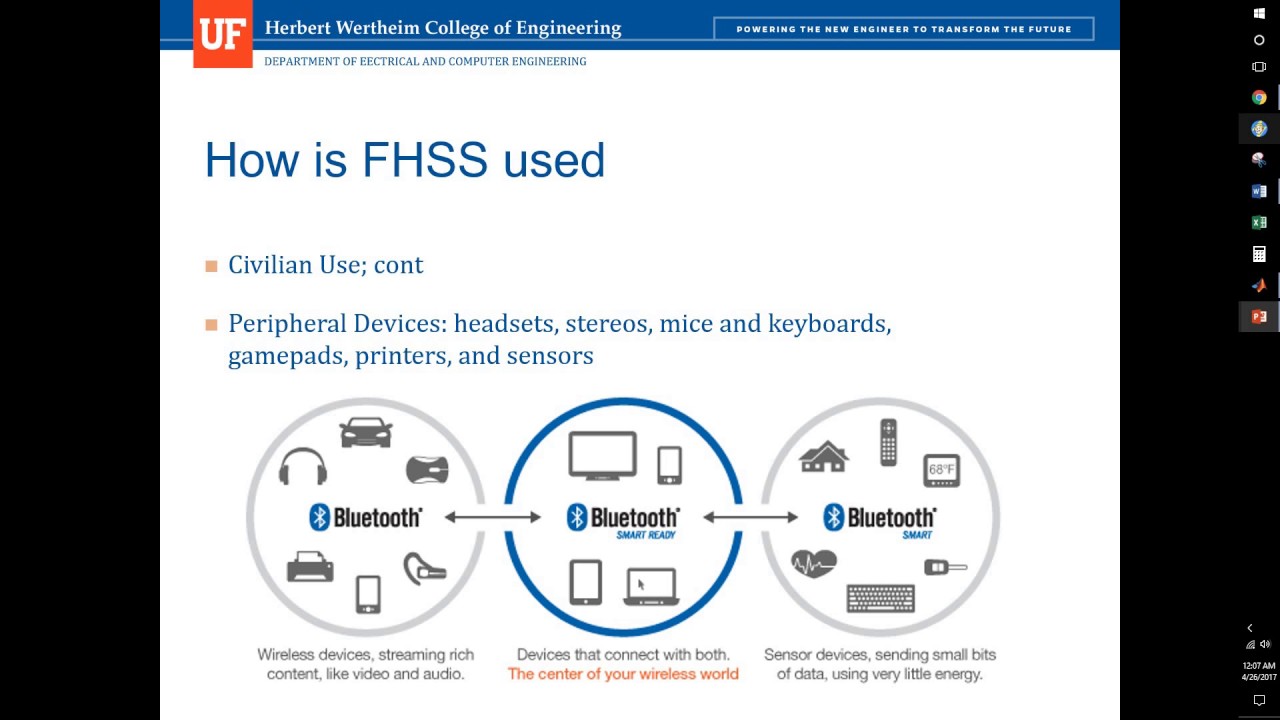
In the US, since the Federal Communications Commission (FCC) amended rules to allow FHSS systems in the unregulated 2.4 GHz band, many consumer devices in that band have employed various FHSS modes. eFCC CFR 47 part 15.247 covers the regulations in the US for 902–928 MHz, 2400–2483.5 MHz, and 5725–5850 MHz bands, and the requirements for frequency hopping [2]
Some walkie-talkies that employ FHSS technology have been developed for unlicensed use on the 900 MHz band. FHSS technology is also used in many hobby radio-controlled transmitters and receivers used for model cars, airplanes, and drones. A type of multiple access is achieved allowing hundreds of transmitter/receiver pairs to be operated simultaneously on the same band in contrast to previous FM or AM radio-controlled systems that had limited simultaneous channels.
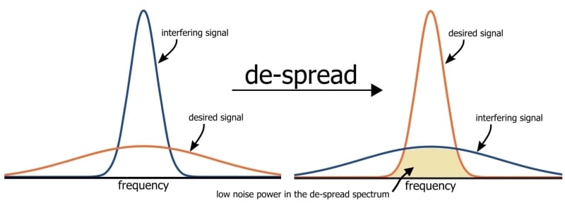
The overall bandwidth required for frequency hopping is much wider than that required to transmit the same information using only one carrier frequency. However, because transmission occurs only on a small portion of this bandwidth at any given time, the instantaneous interference bandwidth is really the same. While providing no extra protection against wideband thermal noise, the frequency-hopping approach reduces the degradation caused by narrowband interference sources.
One of the challenges of frequency-hopping systems is to synchronize the transmitter and receiver. One approach is to have a guarantee that the transmitter will use all the channels in a fixed period of time. The receiver can then find the transmitter by picking a random channel and listening for valid data on that channel. The transmitter's data is identified by a special sequence of data that is unlikely to occur over the segment of data for this channel, and the segment can also have a checksum for integrity checking and further identification. The transmitter and receiver can use fixed tables of frequency-hopping patterns, so that once synchronized they can maintain communication by following the table.
In the US, FCC part 15 on unlicensed spread spectrum systems in the 902–928 MHz and 2.4 GHz bands permits more power than is allowed for non-spread-spectrum systems. Both FHSS and direct-sequence spread-spectrum (DSSS) systems can transmit at 1 watt, a thousand-fold increase from the 1 milliwatt limit on non-spread-spectrum systems. The Federal Communications Commission (FCC) also prescribes a minimum number of frequency channels and a maximum dwell time for each channel.
In 1899 Guglielmo Marconi experimented with frequency-selective reception in an attempt to minimise interference.[3]
The earliest mentions of frequency hopping in open literature are in US patent 725,605 awarded to Nikola Tesla on March 17, 1903 and in radio pioneer Jonathan Zenneck's book Wireless Telegraphy (German, 1908, English translation McGraw Hill, 1915), although Zenneck himself states that Telefunken had already tried it. Nikola Tesla doesn't mention the phrase “frequency hopping” directly, but certainly alludes to it. Entitled Method of Signaling, the patent describes a system that would enable radio communication without any danger of the signals or messages being disturbed, intercepted, interfered with in any way.[4]
The German military made limited use of frequency hopping for communication between fixed command points in World War I to prevent eavesdropping by British forces, who did not have the technology to follow the sequence.[5] Jonathan Zenneck's book Wireless Telegraphy was originally published in German in 1908, but was also translated into English in 1915 as the enemy started using frequency hopping on the front line. Zenneck was a German physicist and electrical engineer who had become interested in radio by attending Tesla lectures on “wireless sciences”. Wireless Telegraphy includes a section on frequency hopping, and, as it became a standard text for many years, it probably introduced the technology to a generation of engineers.[4]
A Polish engineer and inventor, Leonard Danilewicz, came up with the idea in 1929.[6] Several other patents were taken out in the 1930s, including one by Willem Broertjes (U.S. Patent 1,869,659, issued Aug. 2, 1932).
During World War II, the US Army Signal Corps was inventing a communication system called SIGSALY, which incorporated spread spectrum in a single frequency context. However, SIGSALY was a top-secret communications system, so its existence did not become known until the 1980s.
In 1942 actress Hedy Lamarr and composer George Antheil received U.S. Patent 2,292,387 for their "Secret Communications System"[7][8] an early version of frequency hopping using a piano-roll to change among 88 frequencies to make radio-guided torpedoes harder for enemies to detect or to jam, it was rejected by the US Navy then seized as 'alien property' in 1942 (Hedy was Austrian) but filed away with no record of a working device being produced. Lamarr and Antheil's idea was rediscovered in the 1950s during patent searches when private companies were independently developing direct-sequence Code Division Multiple Access, a non-frequency-hopping form of spread-spectrum, and has been cited numerous times since. In 1957 engineers at Sylvania Electronic Systems Division adopted the patented concept, combined with the recently invented transistor.[7] and in 1962 the US Navy finally utilised the technology during the Cuban Missile Crisis, Lamarr and Antheil's patent had since expired. [9]
A practical application of frequency hopping was developed by Ray Zinn, co-founder of Micrel Corporation. Zinn developed a method allowing radio devices to operate without the need to synchronize a receiver with a transmitter. Using frequency hopping and sweep modes, Zinn's method is primarily applied in low data rate wireless applications such as utility metering, machine and equipment monitoring and metering, and remote control. In 2006 Zinn received U.S. Patent 6,996,399 for his "Wireless device and method using frequency hopping and sweep modes."
Adaptive frequency-hopping spread spectrum (AFH) as used in Bluetooth improves resistance to radio frequency interference by avoiding crowded frequencies in the hopping sequence. This sort of adaptive transmission is easier to implement with FHSS than with DSSS.
The key idea behind AFH is to use only the “good” frequencies, by avoiding the "bad" frequency channels—perhaps those "bad" frequency channels are experiencing frequency selective fading, or perhaps some third party is trying to communicate on those bands, or perhaps those bands are being actively jammed. Therefore, AFH should be complemented by a mechanism for detecting good/bad channels.
However, if the radio frequency interference is itself dynamic, then the strategy of “bad channel removal”, applied in AFH might not work well. For example, if there are several colocated frequency-hopping networks (as Bluetooth Piconet), then they are mutually interfering and the strategy of AFH fails to avoid this interference.
The problem of dynamic interference, gradual reduction of available hopping channels and backward compatibility with legacy bluetooth devices was resolved in version 1.2 of the Bluetooth Standard (2003). Such a situation can often happen in the scenarios that use unlicensed spectrum.
In addition, dynamic radio frequency interference is expected to occur in the scenarios related to cognitive radio, where the networks and the devices should exhibit frequency-agile operation.
Chirp modulation can be seen as a form of frequency-hopping that simply scans through the available frequencies in consecutive order to communicate.
Frequency hopping can be superimposed on other modulations or waveforms to enhance the system performance.
^ Torrieri, Don (2018). Principles of Spread-Spectrum Communication Systems, 4th ed.
^ "47 CFR § 15.247 - Operation within the bands 902–928 MHz, 2400–2483.5 MHz, and 5725–5850 MHz". LII / Legal Information Institute. law.cornell.edu. Retrieved 17 December 2019.
^ Kahn, David (2014). How I Discovered World War II's Greatest Spy and Other Stories of Intelligence and Code. Auerbach Publications. p. 158. ISBN 9781466561991.
^ a b eetimes.com: A short history of spread spectrum
^ Denis Winter, Haig's Command - A Reassessment
^ Danilewicz later recalled: "In 1929 we proposed to the General Staff a device of my design for secret radio telegraphy which fortunately did not win acceptance, as it was a truly barbaric idea consisting in constant changes of transmitter frequency. The commission did, however, see fit to grant me 5,000 złotych for executing a model and as encouragement to further work." Cited in Władysław Kozaczuk, Enigma: How the German Machine Cipher Was Broken, and How It Was Read by the Allies in World War II, 1984, p. 27.
^ a b "June 1941: Hedy Lamarr and George Antheil submit patent for radio frequency hopping". APS News. Vol. 20 no. 6. June 2011.
^ Wenner, Melinda (June 3, 2008). "Hedy Lamarr: Not just a pretty face". Scientific American.
^ Commissariat, Tushna (August 1, 2018). "A tale of two lives". Physics World.
Content is available under CC BY-SA 3.0 unless otherwise noted.
This is an experimental demonstration of frequency hopping spread spectrum, a wireless technology that spreads a signal over rapidly changing frequencies. You will learn how a frequency hopping transmitter works and observe a FHSS signal transmitted over the air using software defined radio devices.
It should take about 60-120 minutes to run this experiment, but you will need to have reserved that time in advance. This experiment uses wireless resources (specifically, any one of the sb3 or sb7 sandbox at ORBIT), and you can only use wireless resources on GENI during a reservation.
To reproduce this experiment on GENI, you will need an account on the GENI Portal, and you will need to have joined a project. You should have already uploaded your SSH keys to the portal. The project lead of the project you belong to must have enabled wireless for the project. Finally, you must have reserved time on a sandbox at ORBIT and you must run this experiment during your reserved time. (You may use sb3 or sb7 on ORBIT.)
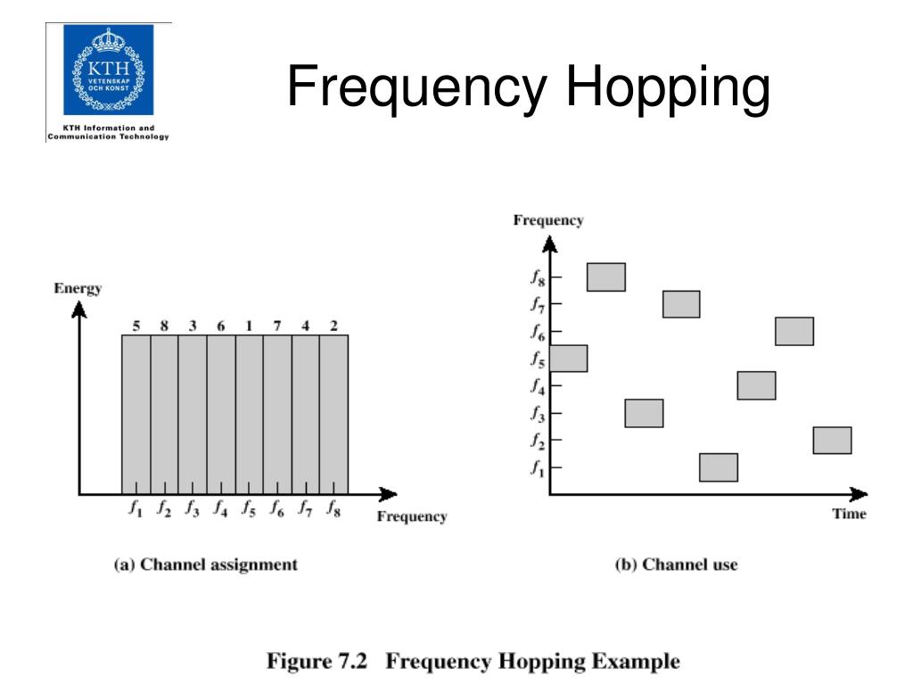
In a frequency-hopping spread spectrum (FHSS) system, the transmitted signal is spread across multiple channels, as shown in Figure 1 below. In the example of Figure 1, the full bandwidth is divided into 8 channels, centered at f1 through f8. The signal "hops" between them in the following sequence: f5, f8, f3, f6, f1, f7, f4, f2.
Figure 1: Frequency hopping example, from William Stallings "Data and Computer Communications".
Figure 2 shows the block diagram of a typical FHSS transmitter. First, digital data is modulated using some digital-to-analog scheme. This baseband signal is then modulated onto a carrier c(t).
Figure 1: Block diagram of FHSS transmitter, from William Stallings "Data and Computer Communications".
The frequency of the carrier c(t), i.e. the sequence of channels, depends on the spreading code, which is generated by a pseudonoise (PN) source. Every TC seconds, the PN source produces a new k-bit value. This value is then used to look up a channel in the channel table, and that determines the frequency of c(t) for that time interval.
For example, consider a system where k=4, and for the first time interval, the PN source generates the value 11012. For that time interval, the signal will be transmitted on channel 13. (The channel table will have 2k-1=24-1=15 entries, indexed from 1 to 15. The PN sequence will repeat itself with a period of 2k-1.)
One popular way to generate a PN sequence is with a linear feedback shift register (LFSR). Consider the LFSR described by the sequence 10011, which can also be described by the following block diagram:
Figure 3: The LFSR corresponding to the generator 10011.
In the FHSS implementation used in this experiment, the spreading code is determined from the state of the registers as shown in Figure 4. After each time instance, the values in each register "shift" as follows (for the LFSR generated by "10011"):
(where the addition in the last item is an XOR operation). Then, the "value" used for that time instance is the decimal value corresponding to the binary digits
e.g. if the values are r3=1, r2=1, r1=0, r0=1, then the channel at f13 will be used (11012=13).
Figure 4: The first four values for the LFSR corresponding to the generator 10011, with initial register values 1111, would be: 15, 7, 14, 5.
For the example above, the complete frequency hopping sequence would be:
f15, f7, f14, f5, f10, f13, f3, f6, f12, f1, f2, f4, f8, f9, f11
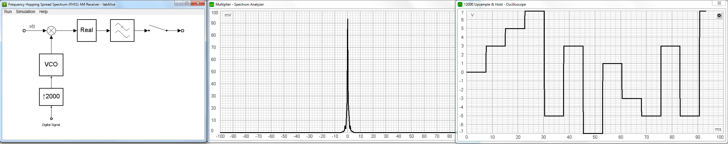
The following video shows the FHSS transmission due to a PN generator with generator (1,0,0,1,1) and initial values (1,1,1,1):
Here's a screenshot of that hopping pattern, annotated with channel numbers:
First, you will have to reserve time on an SDR testbed: either sb3 or sb7 on ORBIT. Log on with your GENI account at http://geni.orbit-lab.org, then click "Control Panel" to access the schedule page.
At your reserved time, open a terminal and log in to the console of the testbed that you have reserved. For example, if you have reserved sandbox 3 on ORBIT,
where GENI-WIRELESS-USERNAME is your wireless username assigned by GENI. This is usually your regular GENI username with a geni- prefix, e.g. geni-ffund. Also specify the path to the key you have uploaded to the GENI Portal as the /PATH/TO/KEY.
If you are using sandbox 7, log in to sb7.orbit-lab.org.
Then, you must load a disk image onto the testbed nodes. From the testbed console, run:
This disk image has the GNU Radio software suite, and the ShinySDR spectrum analyzer, both of which we'll use for this experiment, pre-installed.
This process can take 5-10 minutes. Don't interrupt it in middle - you'll just have to start again, and it will only take longer.
If it's been successful, then once the process finishes running completely you should see output similar to:
Sometimes, transient errors can cause the process to fail - if you haven't successfully imaged 2 nodes, wait a few minutes and try again.
When you've finished loading the disk image, turn on your nodes with
Wait a few minutes for your testbed nodes to turn on, then continue with the experiment.
Open a new terminal window, and run
again, using the correct GENI-WIRELESS-USERNAME, /PATH/TO/KEY, and substituting for sb3.orbit-lab.org the hostname of the console of the testbed that you have reserved.
Then, in that terminal window (which should now be logged in to your testbed console), run
This last command should start the Shiny server, which, when it is running successfully, will say something like:
In a Google Chrome browser window, open the URL that is shown in the Shiny server output. (http://localhost:8100/ShinySDR/).
Configure your Shiny window as follows:
Because FHSS is highly sensitive to frequency, you will also have to calibrate your receiver against the transmitter to adjust for any frequency offset that might exist between them. (See Why is my signal located at an offset from the expected center frequency? for more explanation of the frequency offset phenomenon.)
Open a new terminal, and log in to the testbed console again. From the testbed console, log in to the transmitter node:
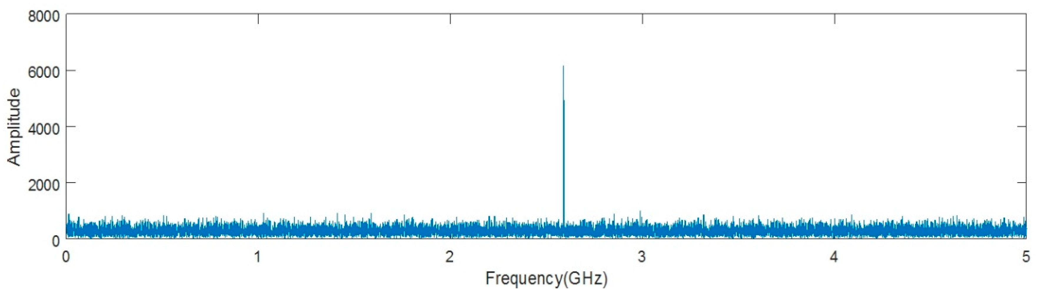
On the transmitter node, generate a reference signal at 2480 MHz using the following command:
While this is running, in the ShinySDR interface, adjust the "Freq.corr. (PPM)" option until you can see the 2480 MHz signal in the center of the display, at the tick mark labeled 2480 MHz:
(If the signal already appears at 2480 MHz, there is no frequency offset and you don't have to adjust the frequency correction.)
When you are satisfied, use Ctrl+C to stop the transmitter on node1-1.
On node1-1, download the FHSS transmitter from GitHub with
To run the FHSS transmitter for the generator "10011", on node1-1 run
(All registers will be initialized with value of 1.)
You should observe the hopping pattern f15, f7, f14, f5, f10, f13, f3, f6, f12, f1, f2, f4, f8, f9, f11:
(Note that for some channels, especially those far from the center frequency, a lower-power "mirror image" of the signal may appear at the same time at its "opposite" channel (relative to the center frequency). This is not a cause for concern; the "mirror" signal can be ignored.)
The offset of each channel relative to the center frequency will be printed in the terminal output, e.g.:
Run the frequency hopping spread spectrum transmitter with the PN code generator "11001". Take a screenshot of the ShinySDR receiver showing the complete hopping pattern (show at least 20 hops). Annotate your screenshot - add the channel numbers at the bottom, similar to this image (although the specific hopping pattern will be different since the generator is different!).
List the hopping sequence for the first 20 hops observed in your screenshot.
Also, create a figure similar to this one, showing how the FHSS transmitter determines the first four channels in the sequence for the generator "11001".
Did you reproduce this experiment? Have useful information to share with other intrepid researchers? Post it here! Comments are posted following moderation.
In this experimental demonstration of the basic operation of a layer 2 switch/bridge, we will see: how to…
This experiment looks at the relationship between data transmission rate, bandwidth, and modulation scheme, as described by the Nyquist…
Pole Riding Porn
German Russian Translation
Secret Bikini
Russian Cock
Bukkake Grannies
Frequency-hopping spread spectrum - Wikipedia
Frequency hopping spread spectrum - NYU - Home
Frequency Hopping Spread Spectrum (FHSS)
What is frequency-hopping spread spectrum? - Definition ...
What is Frequency Hopping Spread Spectrum (FHSS ...
(PDF) FREQUENCY HOPPING SPREAD SPECTRUM FOR IMPROVED SECURITY
Frequency Hopping Spread Spectrum