Vacuum Tube

⚡ 👉🏻👉🏻👉🏻 INFORMATION AVAILABLE CLICK HERE 👈🏻👈🏻👈🏻
This article is about the electronic device. For experiments in an evacuated pipe, see Free fall. For the transport system, see Pneumatic tube. For Blood sampling, see Venipuncture.
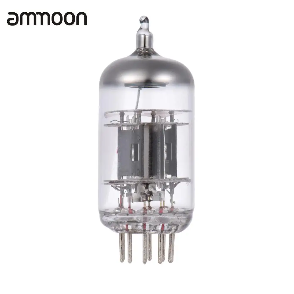
A vacuum tube, an electron tube,[1][2][3] valve (British usage) or tube (North America),[4] is a device that controls electric current flow in a high vacuum between electrodes to which an electric potential difference has been applied.
The type known as a thermionic tube or thermionic valve uses the phenomenon of thermionic emission of electrons from a hot cathode and is used for a number of fundamental electronic functions such as signal amplification and current rectification. Non-thermionic types, such as a vacuum phototube however, achieve electron emission through the photoelectric effect, and are used for such purposes as the detection of light intensities. In both types, the electrons are accelerated from the cathode to the anode by the electric field in the tube.
The simplest vacuum tube, the diode, invented in 1904 by John Ambrose Fleming, contains only a heated electron-emitting cathode and an anode. Electrons can only flow in one direction through the device—from the cathode to the anode. Adding one or more control grids within the tube allows the current between the cathode and anode to be controlled by the voltage on the grids.[5]
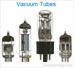
These devices became a key component of electronic circuits for the first half of the twentieth century. They were crucial to the development of radio, television, radar, sound recording and reproduction, long-distance telephone networks, and analog and early digital computers. Although some applications had used earlier technologies such as the spark gap transmitter for radio or mechanical computers for computing, it was the invention of the thermionic vacuum tube that made these technologies widespread and practical, and created the discipline of electronics.[6]
In the 1940s, the invention of semiconductor devices made it possible to produce solid-state devices, which are smaller, more efficient, reliable, durable, safer, and more economical than thermionic tubes. Beginning in the mid-1960s, thermionic tubes were being replaced by the transistor. However, the cathode-ray tube (CRT) remained the basis for television monitors and oscilloscopes until the early 21st century. Thermionic tubes are still used in some applications, such as the magnetron used in microwave ovens, certain high-frequency amplifiers, and amplifiers that audio enthusiasts prefer for their "warmer" tube sound.
Not all electronic circuit valves/electron tubes are vacuum tubes. Gas-filled tubes are similar devices, but containing a gas, typically at low pressure, which exploit phenomena related to electric discharge in gases, usually without a heater.
One classification of thermionic vacuum tubes is by the number of active electrodes. A device with two active elements is a diode, usually used for rectification. Devices with three elements are triodes used for amplification and switching. Additional electrodes create tetrodes, pentodes, and so forth, which have multiple additional functions made possible by the additional controllable electrodes.
Tubes have different functions, such as cathode ray tubes which create a beam of electrons for display purposes (such as the television picture tube) in addition to more specialized functions such as electron microscopy and electron beam lithography. X-ray tubes are also vacuum tubes. Phototubes and photomultipliers rely on electron flow through a vacuum, though in those cases electron emission from the cathode depends on energy from photons rather than thermionic emission. Since these sorts of "vacuum tubes" have functions other than electronic amplification and rectification they are described elsewhere.
Diode: electrons from the hot cathode flow towards the positive anode, but not vice versa
Triode: voltage applied to the grid controls plate (anode) current.
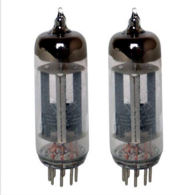
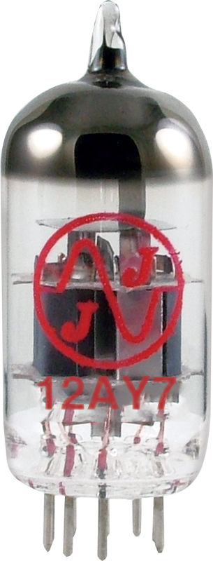
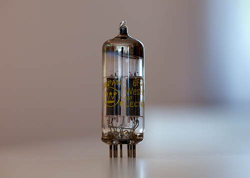
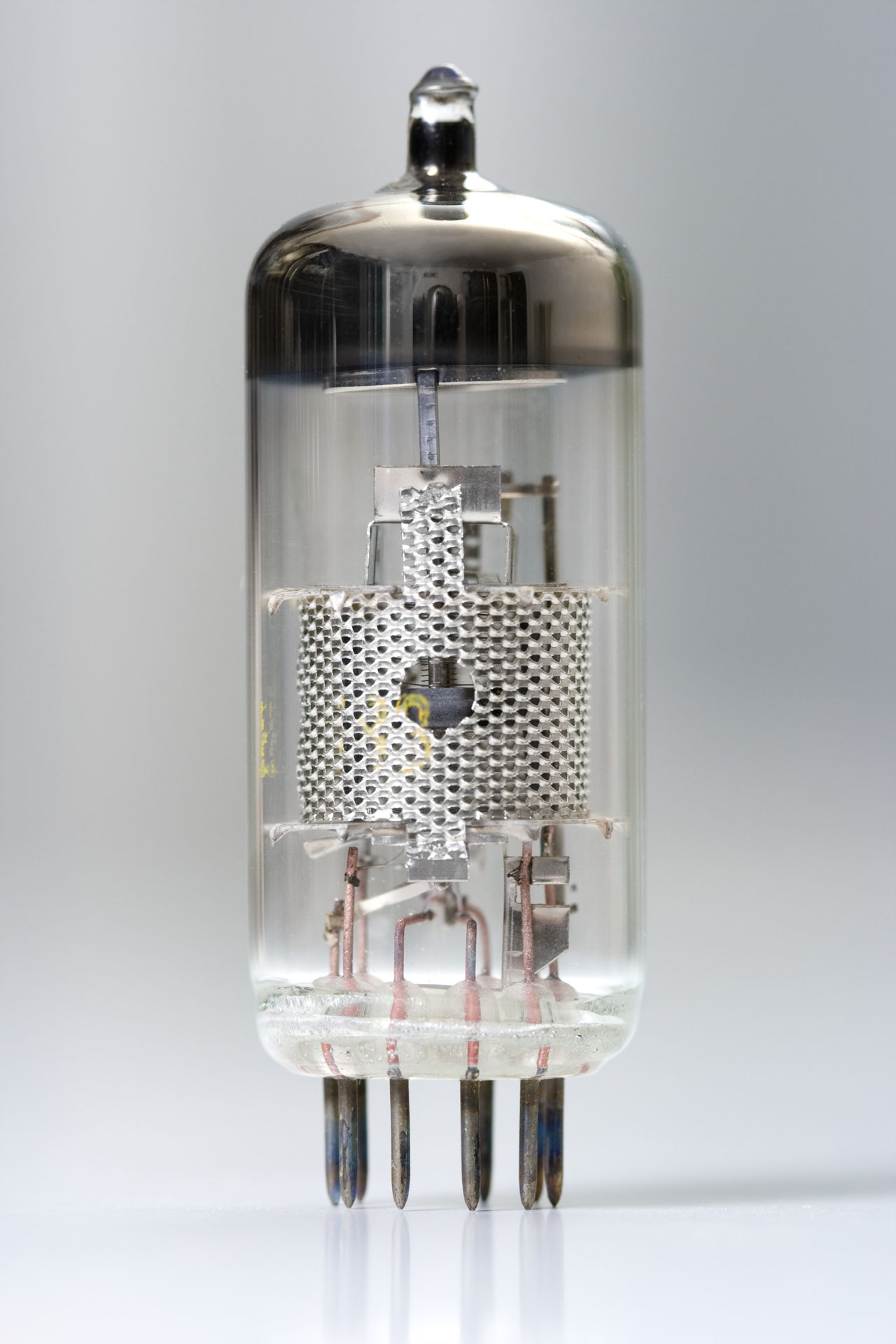
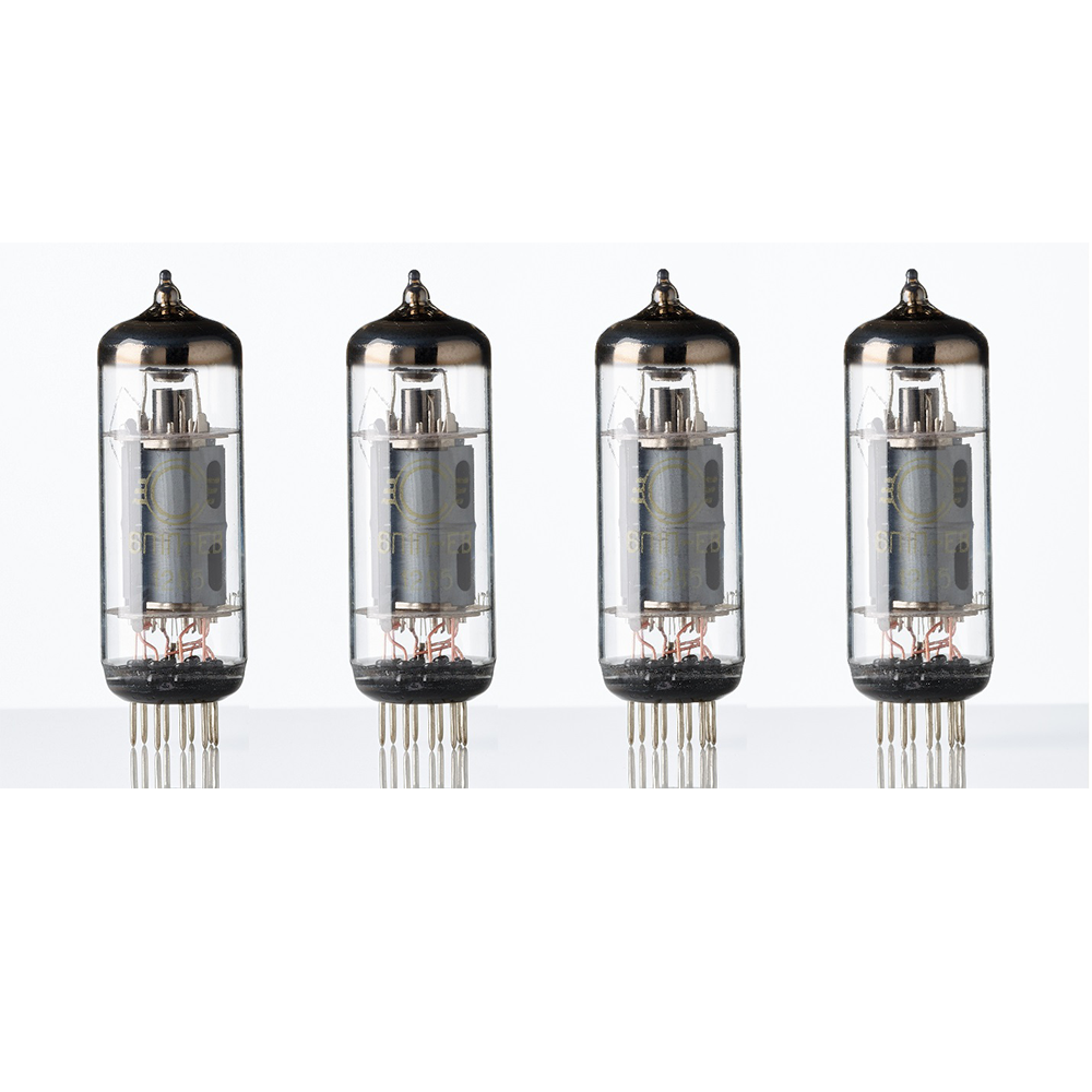
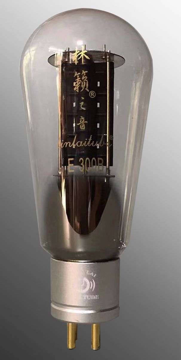
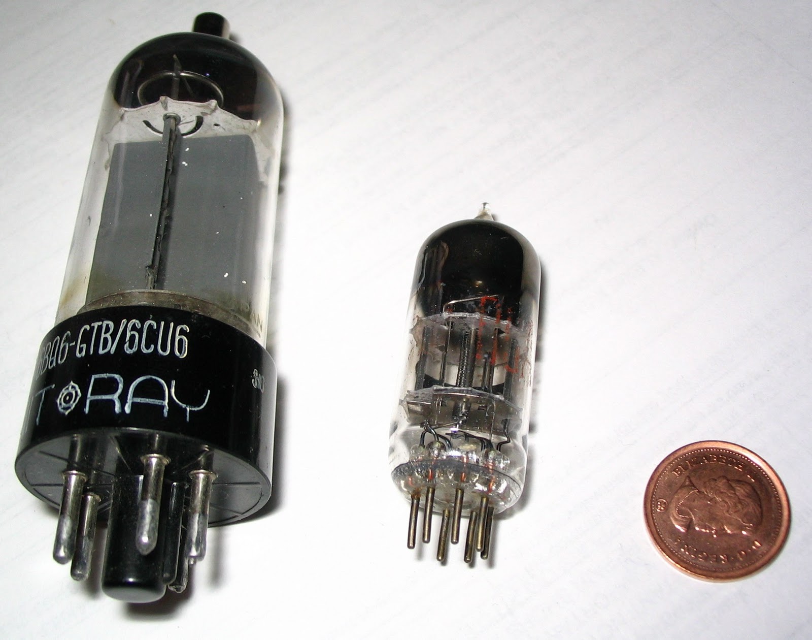
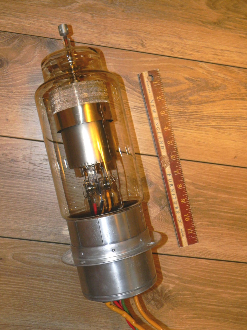
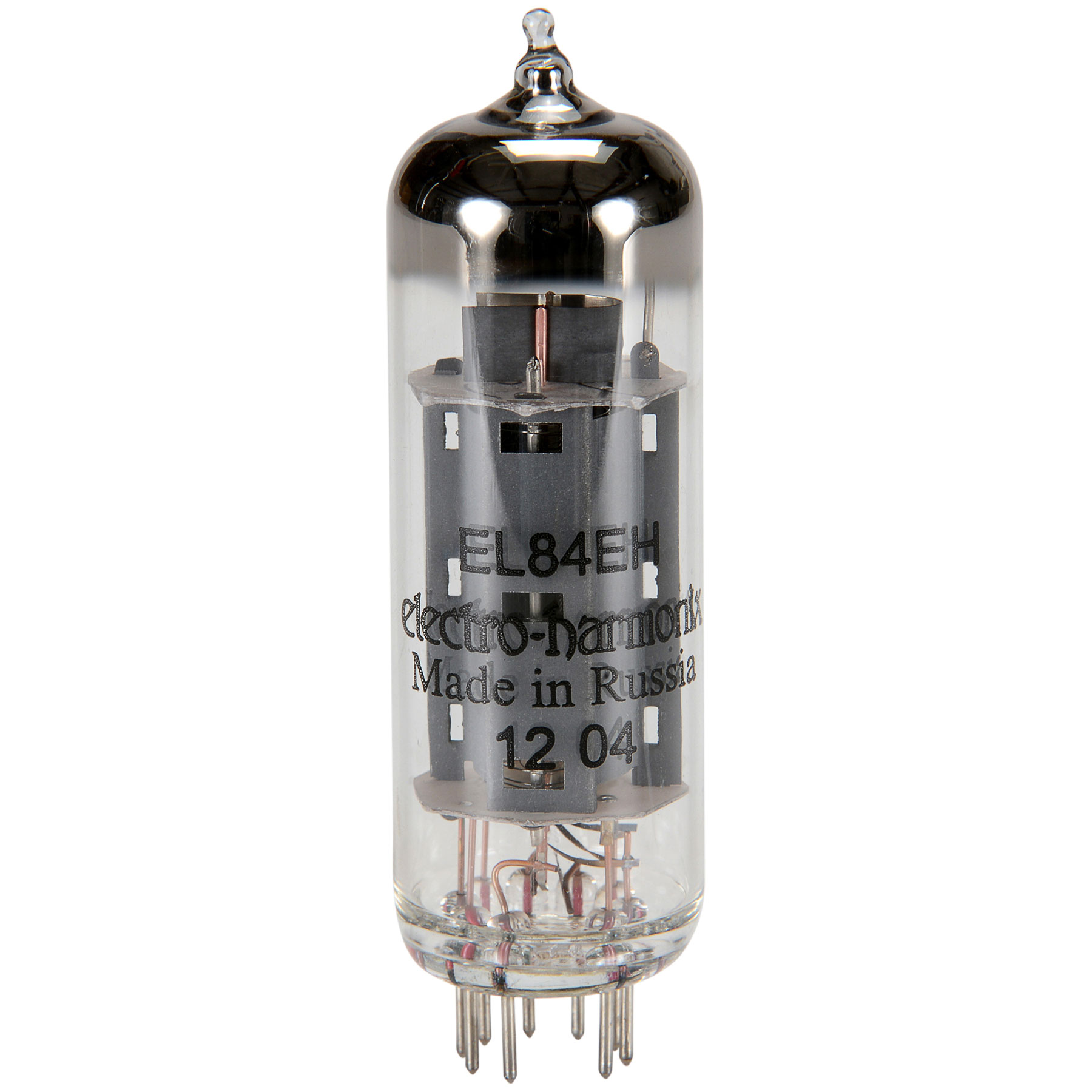
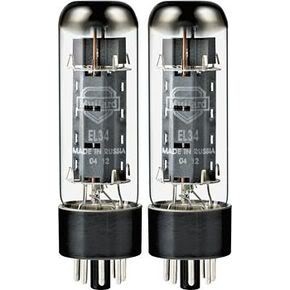
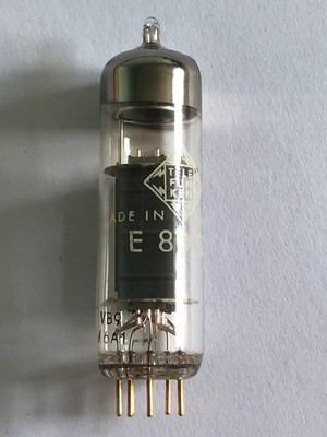
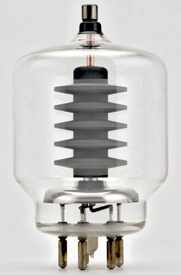
A vacuum tube consists of two or more electrodes in a vacuum inside an airtight envelope. Most tubes have glass envelopes with a glass-to-metal seal based on kovar sealable borosilicate glasses, though ceramic and metal envelopes (atop insulating bases) have been used. The electrodes are attached to leads which pass through the envelope via an airtight seal. Most vacuum tubes have a limited lifetime, due to the filament or heater burning out or other failure modes, so they are made as replaceable units; the electrode leads connect to pins on the tube's base which plug into a tube socket. Tubes were a frequent cause of failure in electronic equipment, and consumers were expected to be able to replace tubes themselves. In addition to the base terminals, some tubes had an electrode terminating at a top cap. The principal reason for doing this was to avoid leakage resistance through the tube base, particularly for the high impedance grid input.[7]:580[8] The bases were commonly made with phenolic insulation which performs poorly as an insulator in humid conditions. Other reasons for using a top cap include improving stability by reducing grid-to-anode capacitance,[9] improved high-frequency performance, keeping a very high plate voltage away from lower voltages, and accommodating one more electrode than allowed by the base. There was even an occasional design that had two top cap connections.
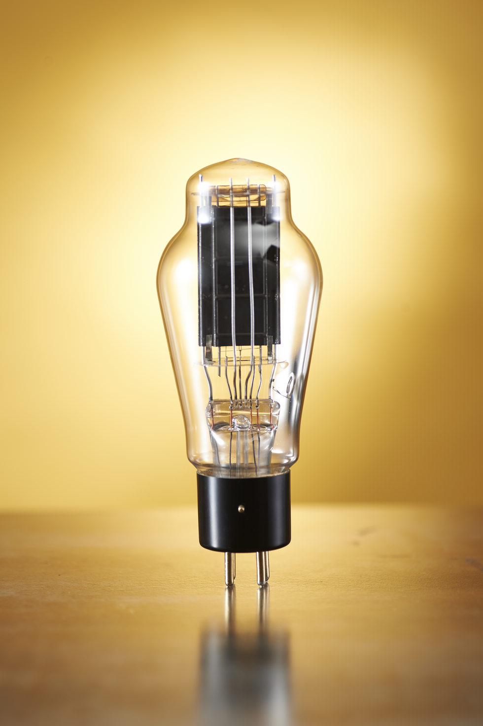
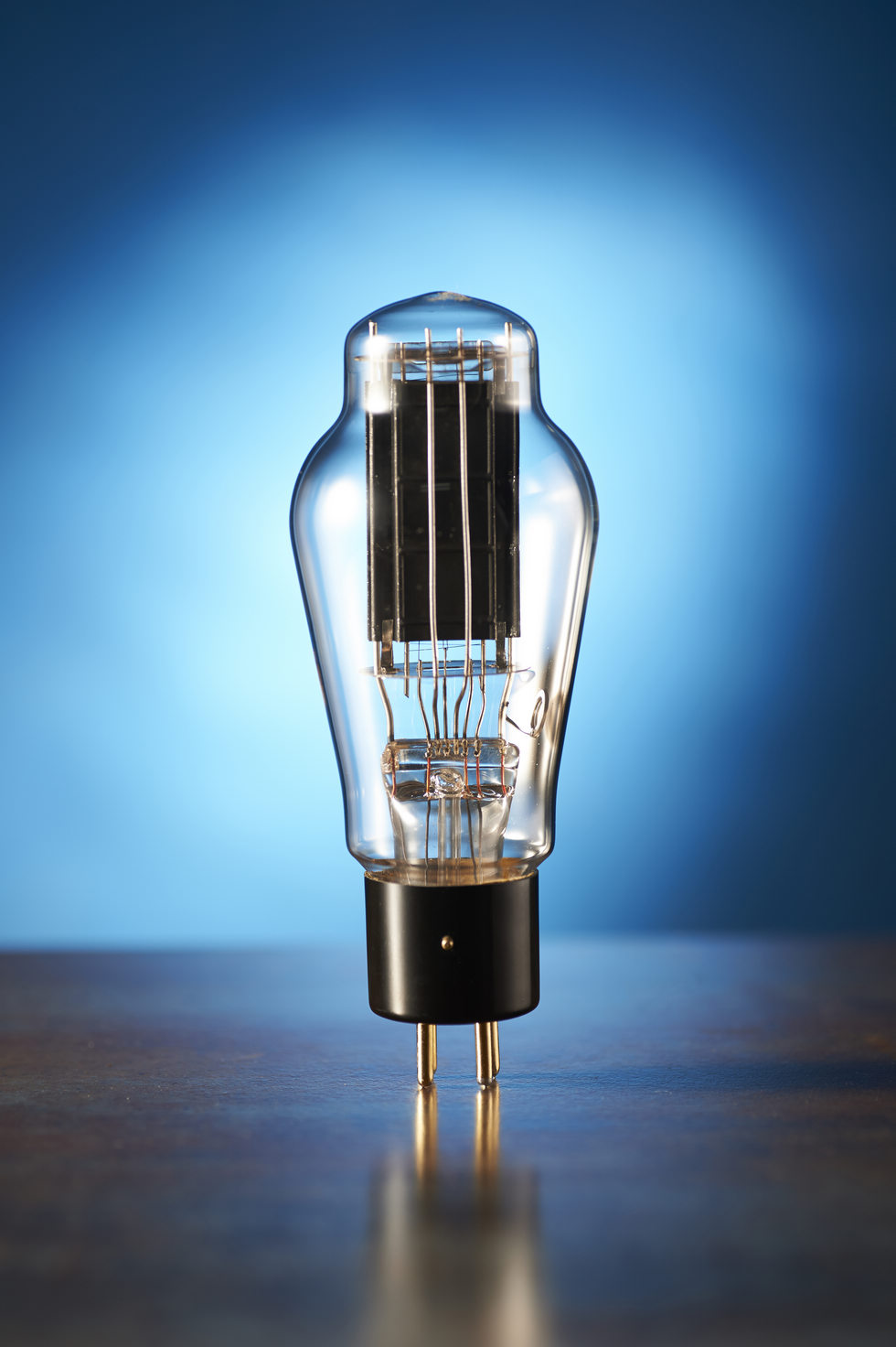
The earliest vacuum tubes evolved from incandescent light bulbs, containing a filament sealed in an evacuated glass envelope. When hot, the filament releases electrons into the vacuum, a process called thermionic emission, originally known as the Edison effect. A second electrode, the anode or plate, will attract those electrons if it is at a more positive voltage. The result is a net flow of electrons from the filament to plate. However, electrons cannot flow in the reverse direction because the plate is not heated and does not emit electrons. The filament (cathode) has a dual function: it emits electrons when heated; and, together with the plate, it creates an electric field due to the potential difference between them. Such a tube with only two electrodes is termed a diode, and is used for rectification. Since current can only pass in one direction, such a diode (or rectifier) will convert alternating current (AC) to pulsating DC. Diodes can therefore be used in a DC power supply, as a demodulator of amplitude modulated (AM) radio signals and for similar functions.
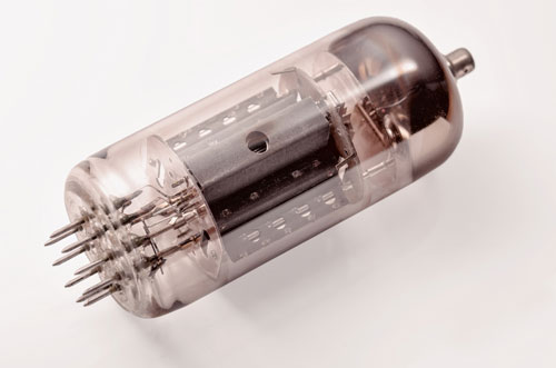
Early tubes used the filament as the cathode; this is called a "directly heated" tube. Most modern tubes are "indirectly heated" by a "heater" element inside a metal tube that is the cathode. The heater is electrically isolated from the surrounding cathode and simply serves to heat the cathode sufficiently for thermionic emission of electrons. The electrical isolation allows all the tubes' heaters to be supplied from a common circuit (which can be AC without inducing hum) while allowing the cathodes in different tubes to operate at different voltages. H. J. Round invented the indirectly heated tube around 1913.[10]
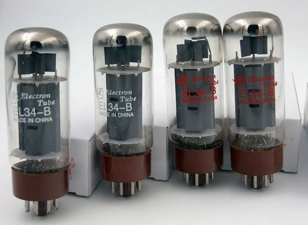
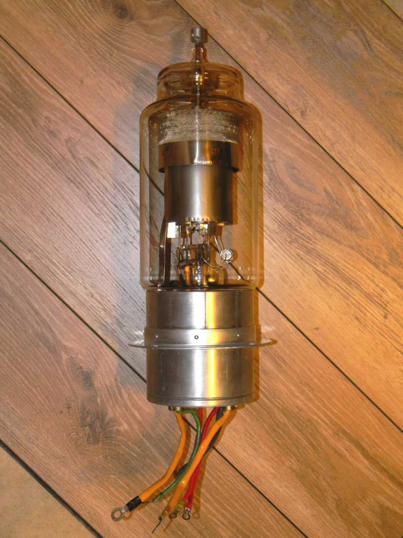
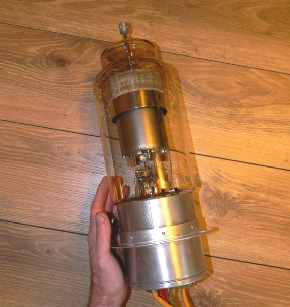
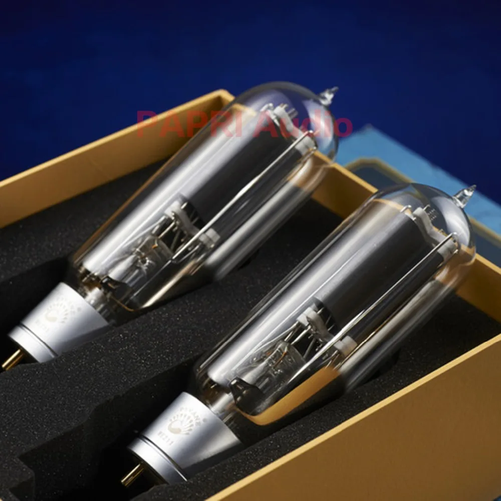
The filaments require constant and often considerable power, even when amplifying signals at the microwatt level. Power is also dissipated when the electrons from the cathode slam into the anode (plate) and heat it; this can occur even in an idle amplifier due to quiescent currents necessary to ensure linearity and low distortion. In a power amplifier, this heating can be considerable and can destroy the tube if driven beyond its safe limits. Since the tube contains a vacuum, the anodes in most small and medium power tubes are cooled by radiation through the glass envelope. In some special high power applications, the anode forms part of the vacuum envelope to conduct heat to an external heat sink, usually cooled by a blower, or water-jacket.
Klystrons and magnetrons often operate their anodes (called collectors in klystrons) at ground potential to facilitate cooling, particularly with water, without high-voltage insulation. These tubes instead operate with high negative voltages on the filament and cathode.
Except for diodes, additional electrodes are positioned between the cathode and the plate (anode). These electrodes are referred to as grids as they are not solid electrodes but sparse elements through which electrons can pass on their way to the plate. The vacuum tube is then known as a triode, tetrode, pentode, etc., depending on the number of grids. A triode has three electrodes: the anode, cathode, and one grid, and so on. The first grid, known as the control grid, (and sometimes other grids) transforms the diode into a voltage-controlled device: the voltage applied to the control grid affects the current between the cathode and the plate. When held negative with respect to the cathode, the control grid creates an electric field that repels electrons emitted by the cathode, thus reducing or even stopping the current between cathode and anode. As long as the control grid is negative relative to the cathode, essentially no current flows into it, yet a change of several volts on the control grid is sufficient to make a large difference in the plate current, possibly changing the output by hundreds of volts (depending on the circuit). The solid-state device which operates most like the pentode tube is the junction field-effect transistor (JFET), although vacuum tubes typically operate at over a hundred volts, unlike most semiconductors in most applications.
The 19th century saw increasing research with evacuated tubes, such as the Geissler and Crookes tubes. The many scientists and inventors who experimented with such tubes include Thomas Edison, Eugen Goldstein, Nikola Tesla, and Johann Wilhelm Hittorf. With the exception of early light bulbs, such tubes were only used in scientific research or as novelties. The groundwork laid by these scientists and inventors, however, was critical to the development of subsequent vacuum tube technology.
Although thermionic emission was originally reported in 1873 by Frederick Guthrie,[11] it was Thomas Edison's apparently independent discovery of the phenomenon in 1883 that became well known. Although Edison was aware of the unidirectional property of current flow between the filament and the anode, his interest (and patent[12]) concentrated on the sensitivity of the anode current to the current through the filament (and thus filament temperature). Little practical use was ever made of this property (however early radios often implemented volume controls through varying the filament current of amplifying tubes). It was only years later that John Ambrose Fleming utilized the rectifying property of the diode tube to detect (demodulate) radio signals, a substantial improvement on the early cat's-whisker detector already used for rectification.
Amplification by vacuum tube became practical only with Lee De Forest's 1907 invention of the three-terminal "audion" tube, a crude form of what was to become the triode.[13] Being essentially the first electronic amplifier,[14] such tubes were instrumental in long-distance telephony (such as the first coast-to-coast telephone line in the US) and public address systems, and introduced a far superior and versatile technology for use in radio transmitters and receivers. The electronics revolution of the 20th century arguably began with the invention of the triode vacuum tube.
The English physicist John Ambrose Fleming worked as an engineering consultant for firms including Edison Swan,[15] Edison Telephone and the Marconi Company. In 1904, as a result of experiments conducted on Edison effect bulbs imported from the United States, he developed a device he called an "oscillation valve" (because it passes current in only one direction). The heated filament, was capable of thermionic emission of electrons that would flow to the plate (or anode) when it was at a positive voltage with respect to the heated cathode. Electrons, however, could not pass in the reverse direction because the plate was not heated and thus not capable of thermionic emission of electrons.
Later known as the Fleming valve, it could be used as a rectifier of alternating current and as a radio wave detector. This greatly improved the crystal set which rectified the radio signal using an early solid-state diode based on a crystal and a so-called cat's whisker, an adjustable point contact. Unlike modern semiconductors, such a diode required painstaking adjustment of the contact to the crystal in order for it to rectify.
The tube was relatively immune to vibration, and thus vastly superior on shipboard duty, particularly for navy ships with the shock of weapon fire commonly knocking the delicate galena off its sensitive point (the tube was in general no more sensitive as a radio detector, but was adjustment free). The diode tube was a reliable alternative for detecting radio signals.
As electronic engineering advanced, notably during World War II, this function of a diode came to be considered as one type of demodulation. While firmly established by history, the term "detector" is not of itself descriptive and should be considered outdated.
Higher-power diode tubes or power rectifiers found their way into power supply applications until they were eventually replaced first by selenium, and later, by silicon rectifiers in the 1960s.
Originally, the only use for tubes in radio circuits was for rectification, not amplification. In 1906, Robert von Lieben filed for a patent[16] for a cathode ray tube which included magnetic deflection. This could be used for amplifying audio signals and was intended for use in telephony equipment. He would later help refine the triode vacuum tube.
However, Lee De Forest is credited with inventing the triode tube in 1907 while experimenting to improve his original (diode) Audion. By placing an additional electrode between the filament (cathode) and plate (anode), he discovered the ability of the resulting device to amplify signals. As the voltage applied to the control grid (or simply "grid") was lowered from the cathode's voltage to somewhat more negative voltages, the amount of current from the filament to the plate would be reduced.
The negative electrostatic field created by the grid in the vicinity of the cathode would inhibit the passage of emitted electrons and reduce the current to the plate. Thus, a few volt difference at the grid would make a large change in the plate current and could lead to a much larger voltage change at the plate; the result was voltage and power amplification. In 1908, De Forest was granted a patent (U.S. Patent 879,532) for such a three-electrode version of his original Audion for use as an electronic amplifier in radio communications. This eventually became known as the triode.
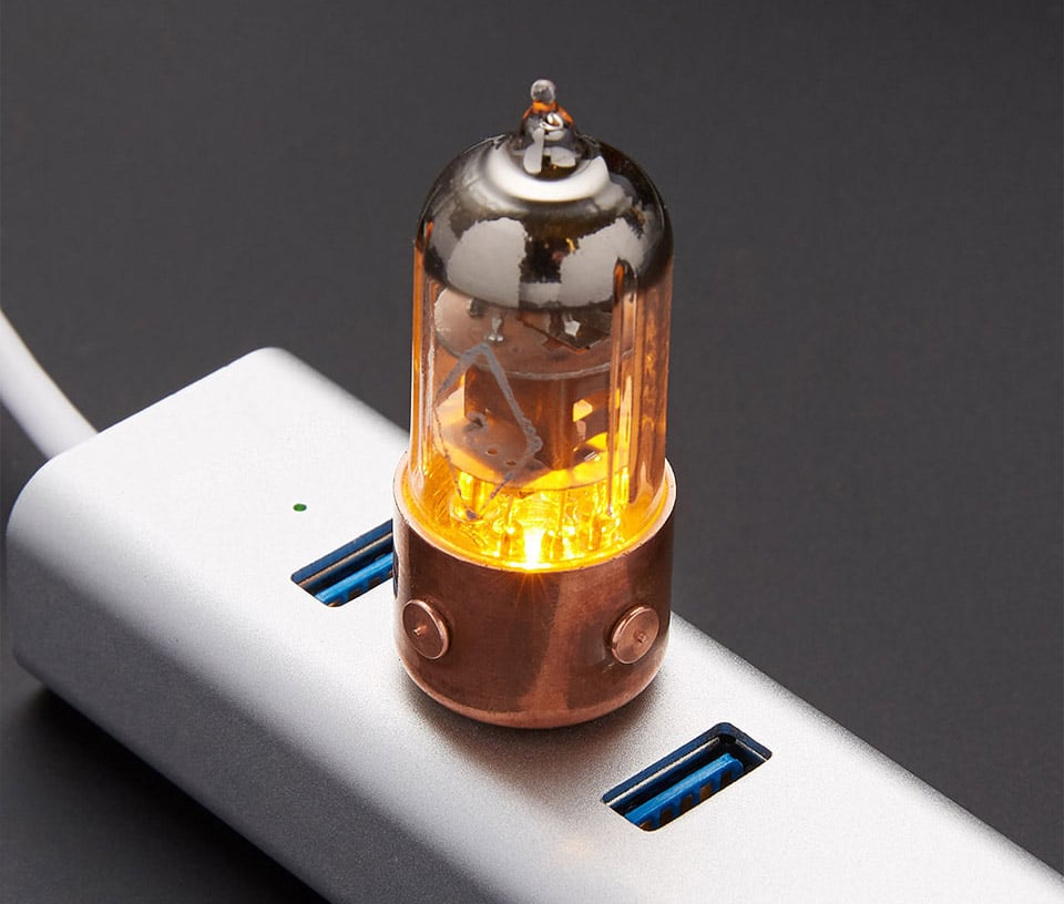
De Forest's original device was made with conventional vacuum technology. The vacuum was not a "hard vacuum" but rather left a very small amount of residual gas. The physics behind the device's operation was also not settled. The residual gas would cause a blue glow (visible ionization) when the plate voltage was high (above about 60 volts). In 1912, De Forest brought the Audion to Harold Arnold in AT&T's engineering department. Arnold recommended that AT&T purchase the patent, and AT&T followed his recommendation. Arnold developed high-vacuum tubes which were tested in the summer of 1913 on AT&T's long-distance network.[17] The high-vacuum tubes could operate at high plate voltages without a blue glow.
Finnish inventor Eric Tigerstedt significantly improved on the original triode design in 1914, while working on his sound-on-film process in Berlin, Germany. Tigerstedt's innovation was to make the electrodes concentric cylinders with the cathode at the centre, thus greatly increasing the collection of emitted electrons at the anode.[18]
Irving Langmuir at the General Electric research laboratory (Schenectady, New York) had improved Wolfgang Gaede's high-vacuum diffusion pump and used it to settle the question of thermionic emission and conduction in a vacuum. Consequently, General Electric started producing hard vacuum triodes (which were branded Pliotrons) in 1915.[19] Langmuir patented the hard vacuum triode, but De Forest and AT&T successfully asserted priority and invalidated the patent.
Pliotrons were closely followed by the French type 'TM' and later the English type 'R' which were in widespread use by the allied military by 1916. Historically, vacuum levels in production vacuum tubes typically ranged from 10 µPa down to 10 nPa.[20]
The triode and its derivatives (tetrodes and pentodes) are transconductance devices, in which the controlling signal applied to the grid is a voltage, and the resulting amplified signal appearing at the anode is a current. Compare this to the behavior of the bipolar junction transistor, in which the controlling signal is a current and the output is also a current.
For vacuum tubes, transconductance or mutual conductance (gm) is defined as the change in the plate(anode)/cathode current divided by the corresponding change in the grid to cathode voltage, with a constant plate(anode) to cathode voltage. Typical values of gm for a small-signal vacuum tube are 1 to 10 millisiemens. It is one of the three 'constants' of a vacuum tube, the other two being its gain μ and plate resistance Rp or Ra. The Van der Bijl equation defines their relationship as follows:
The non-linear operating characteristic of the triode caused early tube audio amplifiers to exhibit harmonic distortion at low volumes. Plotting plate current as a function of applied grid voltage, it was seen that there was a range of grid voltages for which the transfer characteristics were approximately linear.
To use this range, a negative bias voltage had to be applied to the grid to position the DC operating point in the linear region. This was called the idle condition, and the plate current at this point the "idle current". The controlling voltage was superimposed onto the bias voltage, resulting in a linear variation of plate current in response to positive and negative variation of the input voltage around that point.
This concept is called grid bias. Many early radio sets had a third battery called the "C battery" (unrelated to the present-day C cell, for which the letter denotes its size and shape). The C battery's positive terminal was connected to the cathode of the tubes (or "ground" in most circuits) and whose negative terminal supplied this bias voltage to the grids of the tubes.
Later circuits, after tubes were made with heaters isolated from their cathodes, used cathode biasing, avoiding the need for a separate negative power supply. For cathode biasing, a relatively low-value resistor is connected between the cathode and ground. This makes the cathode positive with respect to the grid, which is at ground potential for DC.
However C batteries continued to be included in some
My Moaning Neighbor 2021
Son Fucks Drunk Mother
Pornstars Mom
Porno 3d Pegging
Human 90 Years Old Xxx
Vacuum tube - Wikipedia
How Does a Vacuum Tube Work: Valve Theory » Electronics Notes
vacuum tube - это... Что такое vacuum tube?
vacuum tube - это... Что такое vacuum tube?
List of vacuum tubes - Wikipedia
Vacuum Tube


.jpg/1280px-Vintage_RCA_Blackplate_6L6GC_Vacuum_Tubes_Made_For_McIntosh%252C_Made_In_USA_(15643635699).jpg)