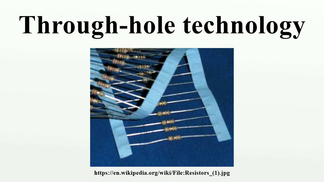
Through Hole Technology

⚡ 👉🏻👉🏻👉🏻 INFORMATION AVAILABLE CLICK HERE 👈🏻👈🏻👈🏻
For a hole passing completely through an object, see Through hole.
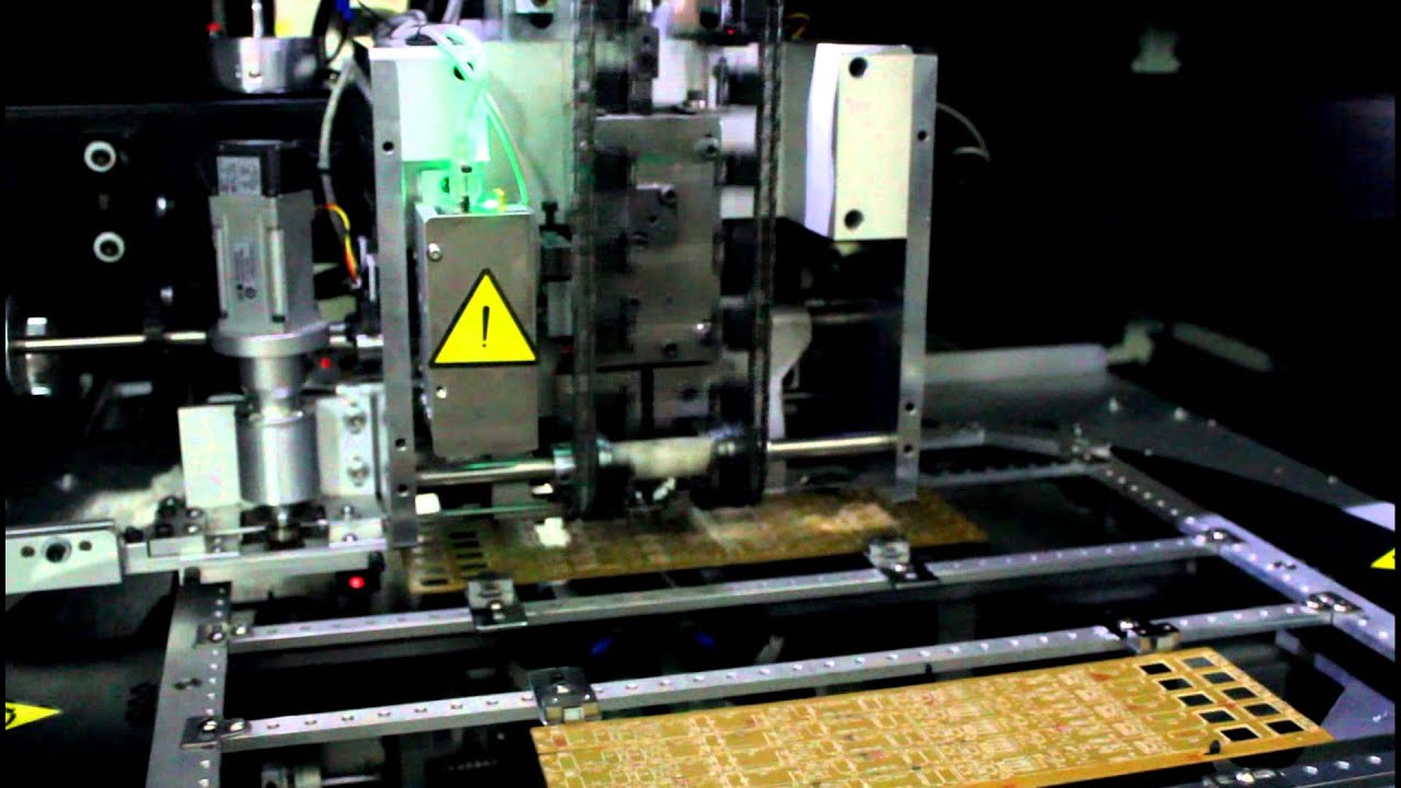
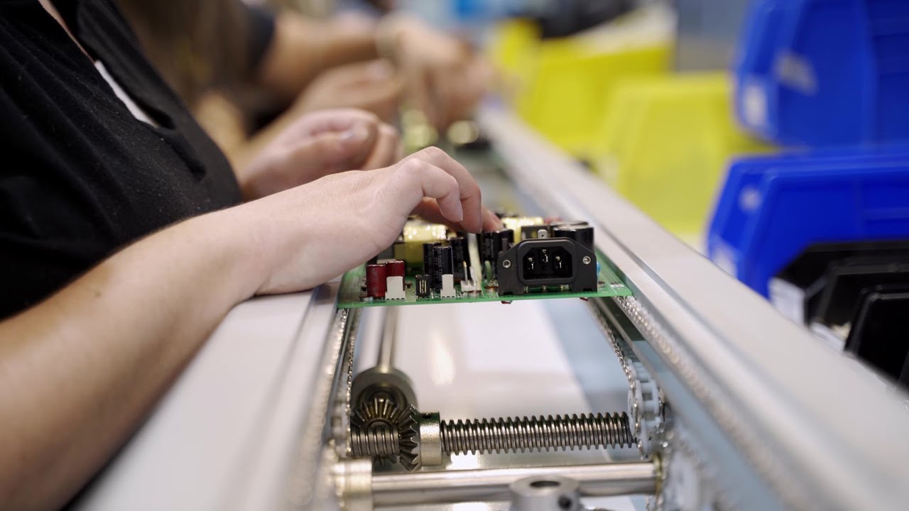
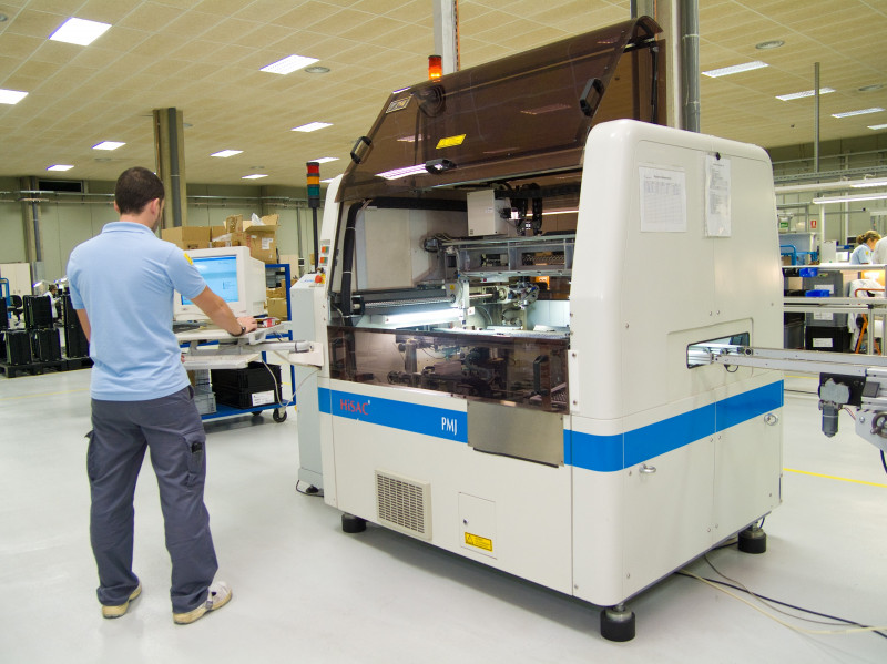
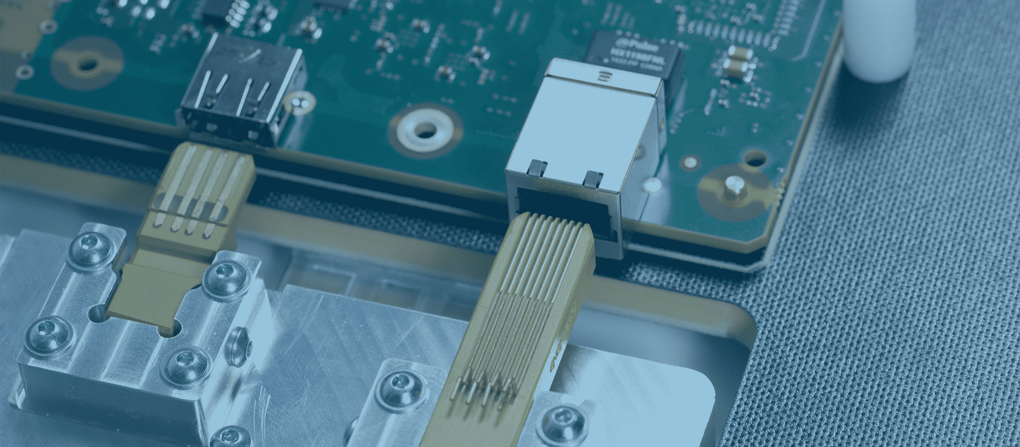
Through-hole technology (also spelled "thru-hole"), refers to the mounting scheme used for electronic components that involves the use of leads on the components that are inserted into holes drilled in printed circuit boards (PCB) and soldered to pads on the opposite side either by manual assembly (hand placement) or by the use of automated insertion mount machines.[1][2]
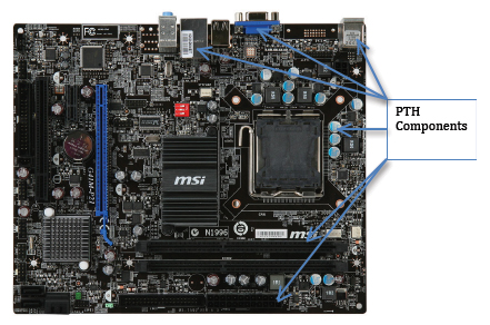
Through-hole technology almost completely replaced earlier electronics assembly techniques such as point-to-point construction. From the second generation of computers in the 1950s until surface-mount technology (SMT) became popular in the late 1980s, every component on a typical PCB was a through-hole component. PCBs initially had tracks printed on one side only, later both sides, then multi-layer boards were in use. Through holes became plated-through holes (PTH) in order for the components to make contact with the required conductive layers. Plated-through holes are no longer required with SMT boards for making the component connections, but are still used for making interconnections between the layers and in this role are more usually called vias.[2]
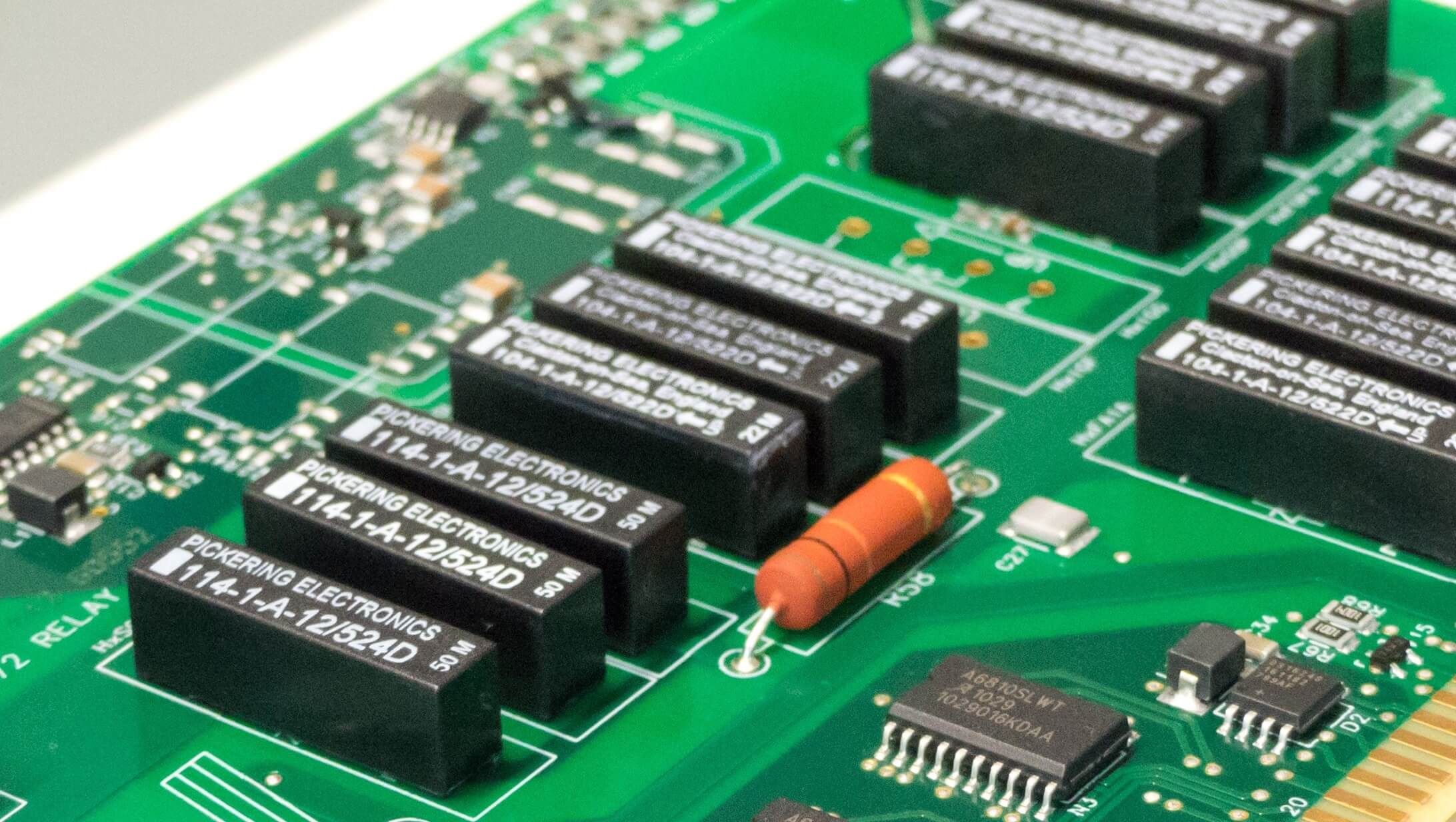
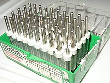
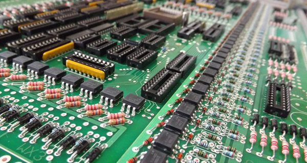
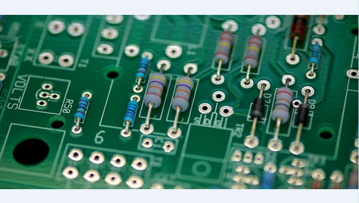
Components with wire leads are generally used on through-hole boards. Axial leads protrude from each end of a typically cylindrical or elongated box-shaped component, on the geometrical axis of symmetry. Axial-leaded components resemble wire jumpers in shape, and can be used to span short distances on a board, or even otherwise unsupported through an open space in point-to-point wiring. Axial components do not protrude much above the surface of a board, producing a low-profile or flat configuration when placed "lying down" or parallel to the board.[3][4][5]
Radial leads project more or less in parallel from the same surface or aspect of a component package, rather than from opposite ends of the package. Originally, radial leads were defined as more-or-less following a radius of a cylindrical component (such as a ceramic disk capacitor).[5] Over time, this definition was generalized in contrast to axial leads, and took on its current form. When placed on a board, radial components "stand up" perpendicular,[3][4] occupying a smaller footprint on sometimes-scarce "board real estate", making them useful in many high-density designs. The parallel leads projecting from a single mounting surface gives radial components an overall "plugin nature", facilitating their use in high-speed automated component insertion ("board-stuffing") machines.
When needed, an axial component can be effectively converted into a radial component, by bending one of its leads into a "U" shape so that it ends up close to and parallel with the other lead.[4] Extra insulation with heat-shrink tubing may be used to prevent shorting out on nearby components. Conversely, a radial component can be pressed into service as an axial component by separating its leads as far as possible, and extending them into an overall length-spanning shape. These improvisations are often seen in breadboard or prototype construction, but are deprecated for mass production designs. This is because of difficulties in use with automated component placement machinery, and poorer reliability because of reduced vibration and mechanical shock resistance in the completed assembly.
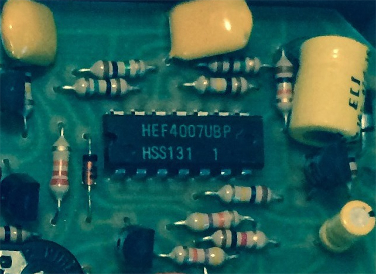
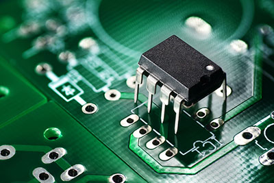
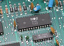
For electronic components with two or more leads, for example, diodes, transistors, ICs, or resistor packs, a range of standard-sized semiconductor packages are used, either directly onto the PCB or via a socket.
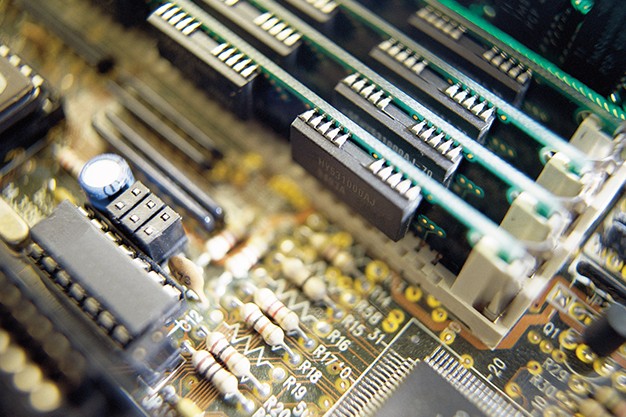
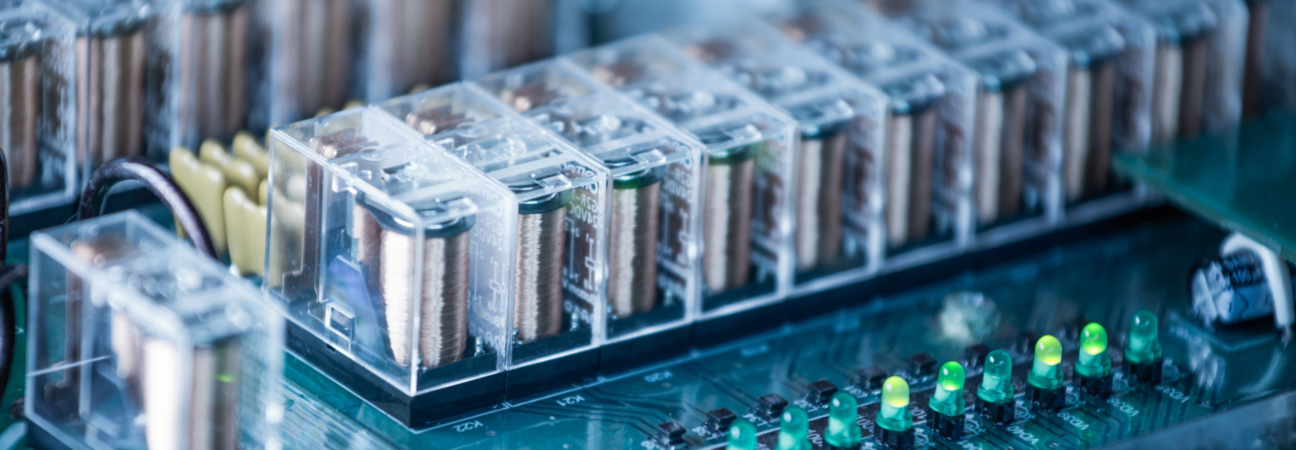
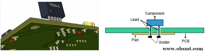
While through-hole mounting provides strong mechanical bonds when compared to SMT techniques, the additional drilling required makes the boards more expensive to produce. They also limit the available routing area for signal traces on layers immediately below the top layer on multilayer boards since the holes must pass through all layers to the opposite side. To that end, through-hole mounting techniques are now usually reserved for bulkier or heavier components such as electrolytic capacitors or semiconductors in larger packages such as the TO-220 that require the additional mounting strength, or for components such as plug connectors or electromechanical relays that require great strength in support.[4]
Design engineers often prefer the larger through-hole rather than surface mount parts when prototyping, because they can be easily used with breadboard sockets. However, high-speed or high-frequency designs may require SMT technology to minimize stray inductance and capacitance in wire leads, which would impair circuit function. Ultra-compact designs may also dictate SMT construction, even in the prototype phase of design.
Through-hole components are ideal for prototyping circuits with breadboards using microprocessors such as Arduino or PICAXE. These components are large enough to be easy to use and solder by hand.
^ Electronic Packaging:Solder Mounting Technologies in K.H. Buschow et al (ed), Encyclopedia of Materials:Science and Technology, Elsevier, 2001 ISBN 0-08-043152-6, pages 2708-2709
^ a b Horowitz, Paul; Hill, Winfield (1989). The art of electronics (PDF) (2nd ed.). Cambridge [u.a.]: Cambridge Univ. Press. ISBN 9780521370950.
^ a b "All About Capacitors". Beavis Audio Research. Retrieved 2013-05-16.
^ a b c d "What Is an Axial Lead?". wiseGEEK: clear answers for common. Conjecture Corporation. Retrieved 2013-05-16.
^ a b Bilotta, Anthony J. (1985). Connections in electronic assemblies. New York: M. Dekker. p. 205. ISBN 9780824773199.
Content is available under CC BY-SA 3.0 unless otherwise noted.
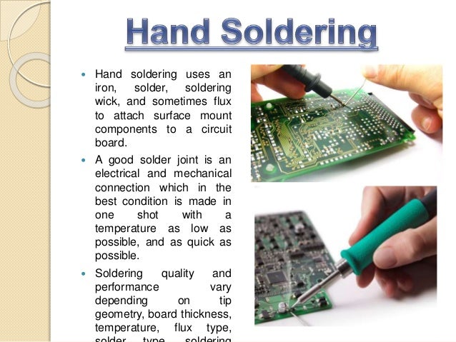
Through-hole technology is the mounting process by which component leads are placed into the drilled holes of a bare printed circuit board (PCB) and soldered to the pads on the opposite side. This can be done using manual assembly or automated insertion mount machines.
Through-hole technology became popular in the construction of second-generation computers in the 1950s. PCBs started as a one-sided board, then two-sided, until multi-layer boards became popular. Through-hole mounting was the standard practice until surface mount technology (SMT) became popular in the 1980s.
The advent of surface mount technology was initially thought to have made through-hole technology obsolete, but it proved to be a very resilient technology because of its distinct advantages and niche reliability.
Advantages of Through-Hole Technology
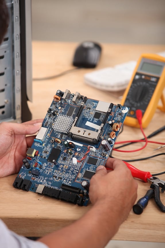
Through-hole components proved to be more reliable in products requiring stronger connections between the layers. Through-hole component leads are capable of withstanding a lot more environmental stress because they run through the board while SMT components are only secured by the solder of the board’s surface. This advantage makes through-hole technology the preferred process in aerospace and military products that endure high temperatures, extreme accelerations, and collisions. Through-hole technology is also used in applications that require testing and prototyping because of the manual replacement and adjustment capabilities.
Through-hole technology’s need for strong mechanical bonds makes the boards more expensive than SMT boards. That is why through-hole technology is now reserved mostly for heavier or bulkier components such as semiconductors or electrolytic capacitors in larger packages that need more mounting strength. They are also popular for elements like plug connectors that need a lot of muscle for reinforcement.
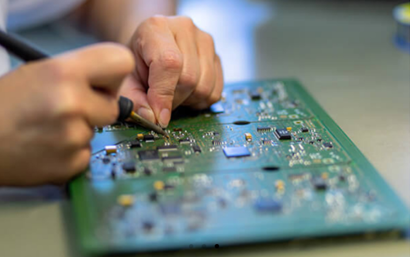
Most design engineers and manufacturers, including EMS Solutions, prefer the reliable through-hole technology to SMT when they are prototyping because through-hole can be used with breadboard sockets. Through-hole, however, is not appropriate for high frequency or high-speed designs that require minimal stray capacitance and inductance in wire leads.In addition, through-hole is not recommended for ultra-compact designs, which require SMT construction, even in the prototype stage.
Please complete this short form and you will receive a confirmation email with more info to complete your quote request. (*required fields)
Services Interested In:
Printed Circuit Assemblies
Cable Assemblies
Box Build Assemblies
New Product Introductions
Test Solutions
Other
"The best manufacturing facility in the intermountain area, no doubt" – Leading wireless company
"A true manufacturing partner" – Leading logistics Equipment Company
"We have enjoyed a very long term relationship that has allowed us to expand our business and better serve our customers" – Leading communication Equipment Company
Electronics Manufacturing Services » Through-Hole Technology and Its Advantages
© Copyright EMS Solutions
Website optimized by SEOnational.com
Booty Babes Com
Porno Ass Curvy
Solo Yandex Ru
Vintage Trainingsjacke Adidas
Seks Erotika Mom And Son
Through-hole technology - Wikipedia
Through-Hole Technology and Its Advantages - EMS Solutions
Through Hole Technology - Sinovoltaics
THROUGH-HOLE TECHNOLOGY – Advanced Technology and ...
The Pros and Cons of Through-Hole Technology
PCB assembly: hand-mount technology | Semecs
Through Hole Technology and PCB Assembly Services
Through Hole Technology