Through Hole

🛑 👉🏻👉🏻👉🏻 INFORMATION AVAILABLE CLICK HERE👈🏻👈🏻👈🏻
From Wikipedia, the free encyclopedia
For a hole passing completely through an object, see Through hole .
^ Electronic Packaging:Solder Mounting Technologies in K.H. Buschow et al (ed), Encyclopedia of Materials:Science and Technology , Elsevier, 2001 ISBN 0-08-043152-6 , pages 2708-2709
^ Jump up to: a b Horowitz, Paul; Hill, Winfield (1989). The art of electronics (PDF) (2nd ed.). Cambridge [u.a.]: Cambridge Univ. Press. ISBN 9780521370950 .
^ Jump up to: a b "All About Capacitors" . Beavis Audio Research . Retrieved 2013-05-16 .
^ Jump up to: a b c d "What Is an Axial Lead?" . wiseGEEK: clear answers for common . Conjecture Corporation . Retrieved 2013-05-16 .
^ Jump up to: a b Bilotta, Anthony J. (1985). Connections in electronic assemblies . New York: M. Dekker. p. 205. ISBN 9780824773199 .
Wiki Loves Monuments: your chance to support Russian cultural heritage!
Photograph a monument and win!
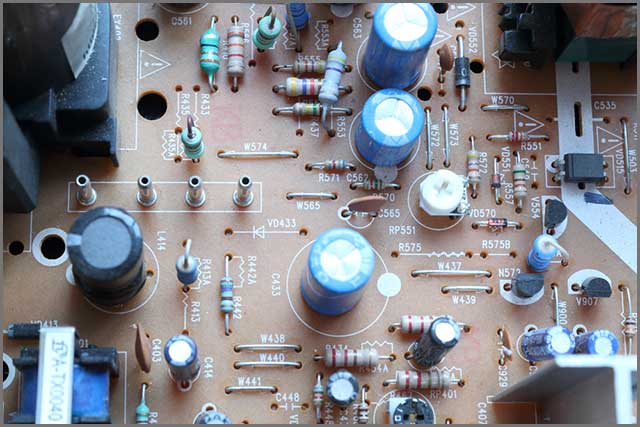
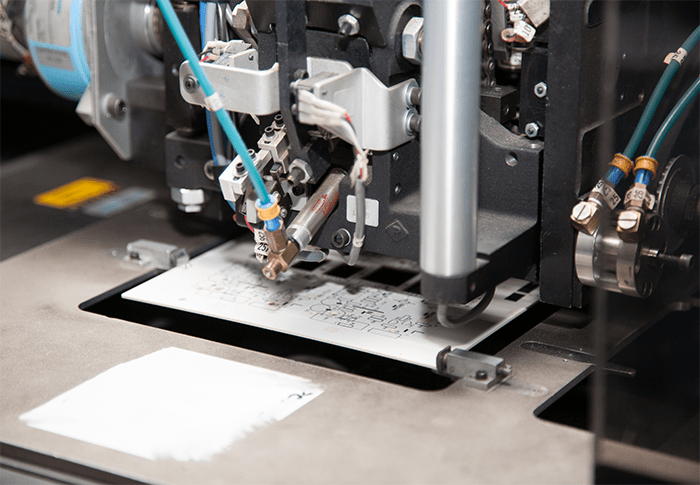
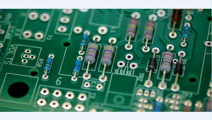
Through-hole technology (also spelled " thru-hole "), refers to the mounting scheme used for electronic components that involves the use of leads on the components that are inserted into holes drilled in printed circuit boards (PCB) and soldered to pads on the opposite side either by manual assembly (hand placement) or by the use of automated insertion mount machines . [1] [2]
Through-hole technology almost completely replaced earlier electronics assembly techniques such as point-to-point construction . From the second generation of computers in the 1950s until surface-mount technology (SMT) became popular in the late 1980s, every component on a typical PCB was a through-hole component. PCBs initially had tracks printed on one side only, later both sides, then multi-layer boards were in use. Through holes became plated-through holes (PTH) in order for the components to make contact with the required conductive layers. Plated-through holes are no longer required with SMT boards for making the component connections, but are still used for making interconnections between the layers and in this role are more usually called vias . [2]
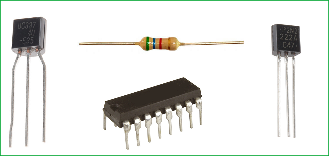
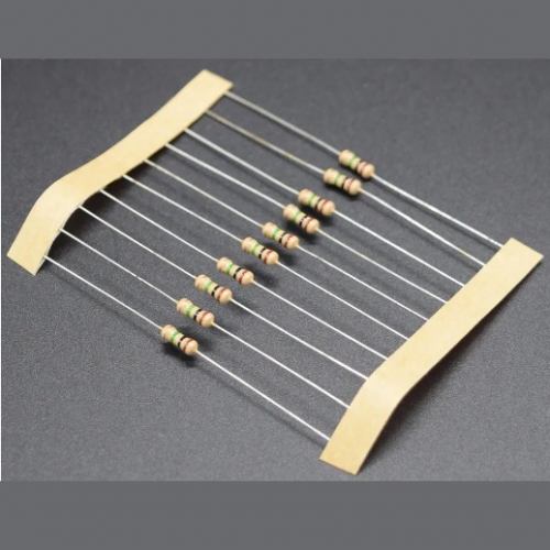
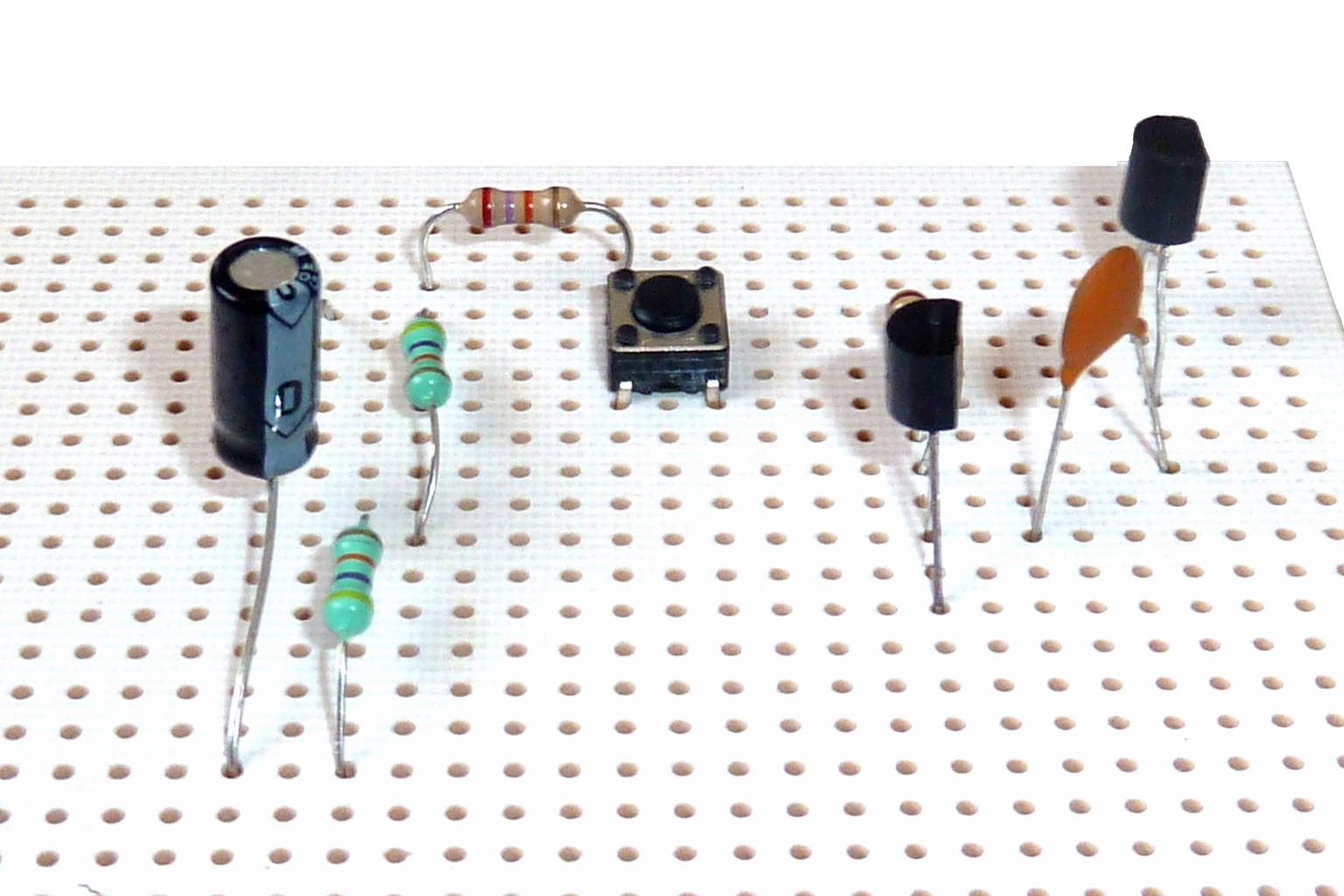
Components with wire leads are generally used on through-hole boards. Axial leads protrude from each end of a typically cylindrical or elongated box-shaped component, on the geometrical axis of symmetry . Axial-leaded components resemble wire jumpers in shape, and can be used to span short distances on a board, or even otherwise unsupported through an open space in point-to-point wiring . Axial components do not protrude much above the surface of a board, producing a low-profile or flat configuration when placed "lying down" or parallel to the board. [3] [4] [5]
Radial leads project more or less in parallel from the same surface or aspect of a component package, rather than from opposite ends of the package. Originally, radial leads were defined as more-or-less following a radius of a cylindrical component (such as a ceramic disk capacitor ). [5] Over time, this definition was generalized in contrast to axial leads, and took on its current form. When placed on a board, radial components "stand up" perpendicular, [3] [4] occupying a smaller footprint on sometimes-scarce "board real estate", making them useful in many high-density designs. The parallel leads projecting from a single mounting surface gives radial components an overall "plugin nature", facilitating their use in high-speed automated component insertion ("board-stuffing") machines.
When needed, an axial component can be effectively converted into a radial component, by bending one of its leads into a "U" shape so that it ends up close to and parallel with the other lead. [4] Extra insulation with heat-shrink tubing may be used to prevent shorting out on nearby components. Conversely, a radial component can be pressed into service as an axial component by separating its leads as far as possible, and extending them into an overall length-spanning shape. These improvisations are often seen in breadboard or prototype construction, but are deprecated for mass production designs. This is because of difficulties in use with automated component placement machinery , and poorer reliability because of reduced vibration and mechanical shock resistance in the completed assembly.
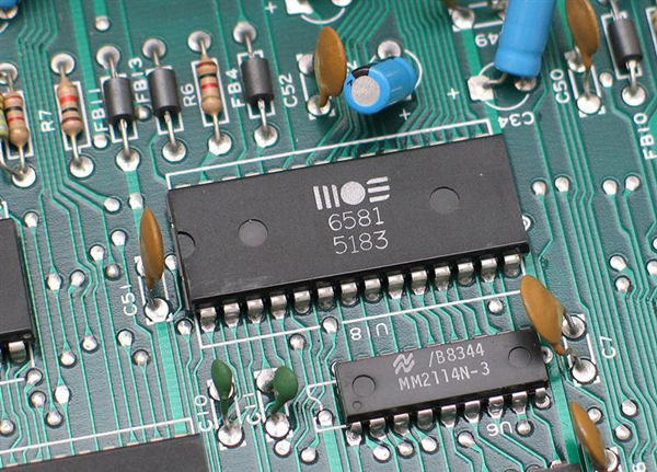
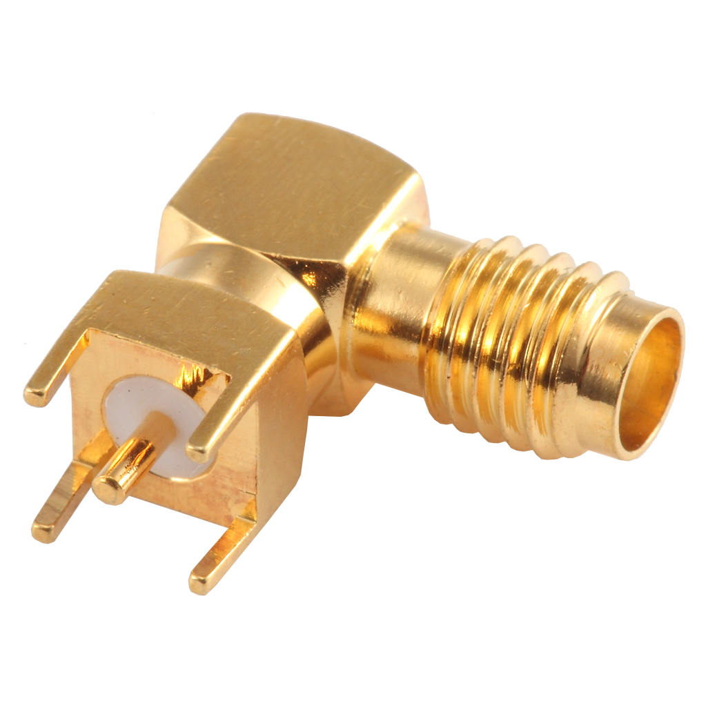
For electronic components with two or more leads, for example, diodes, transistors, ICs, or resistor packs, a range of standard-sized semiconductor packages are used, either directly onto the PCB or via a socket.
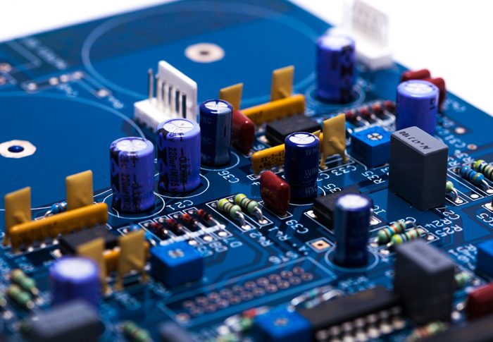
While through-hole mounting provides strong mechanical bonds when compared to SMT techniques, the additional drilling required makes the boards more expensive to produce. They also limit the available routing area for signal traces on layers immediately below the top layer on multilayer boards since the holes must pass through all layers to the opposite side. To that end, through-hole mounting techniques are now usually reserved for bulkier or heavier components such as electrolytic capacitors or semiconductors in larger packages such as the TO-220 that require the additional mounting strength, or for components such as plug connectors or electromechanical relays that require great strength in support. [4]
Design engineers often prefer the larger through-hole rather than surface mount parts when prototyping, because they can be easily used with breadboard sockets . However, high-speed or high-frequency designs may require SMT technology to minimize stray inductance and capacitance in wire leads, which would impair circuit function. Ultra-compact designs may also dictate SMT construction, even in the prototype phase of design.
Through-hole components are ideal for prototyping circuits with breadboards using microprocessors such as Arduino or PICAXE . These components are large enough to be easy to use and solder by hand.
Stay up to date with news and promotions by signing up for our monthly newsletter.
Send
Copyright © 2012 - 2021, Smart Prototyping, All Rights Reserved.
Pop quiz: Which hole is the through hole?
A hole of many names--clearance hole, thru-hole, via, plated thru-hole, etc--, a through hole (TH) is a hole in a PCB that is either drilled, reamed, or milled all the way through. Which means if you guessed the hole in the center of the image was the TH, you’re right. The hole on the left is a blind hole and on the right, is an interrupted hole.
Through hole technology once dominated as the electronics assembly technique from the 1950’s until the 1980’s when SMT (surface-mount technology) rose to prominence. During that period, every component on a PCB was a through hole component.
Since then, SMT’s have enjoyed wide adoption for their advantages over TH components and changing technology requirements. However, THs are still a common method used to deliver electrical connections from one layer to another (think breakout boards and header pins).
PCBs originally had tracing on one side, then on both sides, later multi-layers were added. Vias, or plated through holes (PTH), were then designed to make contact with conductive layers.
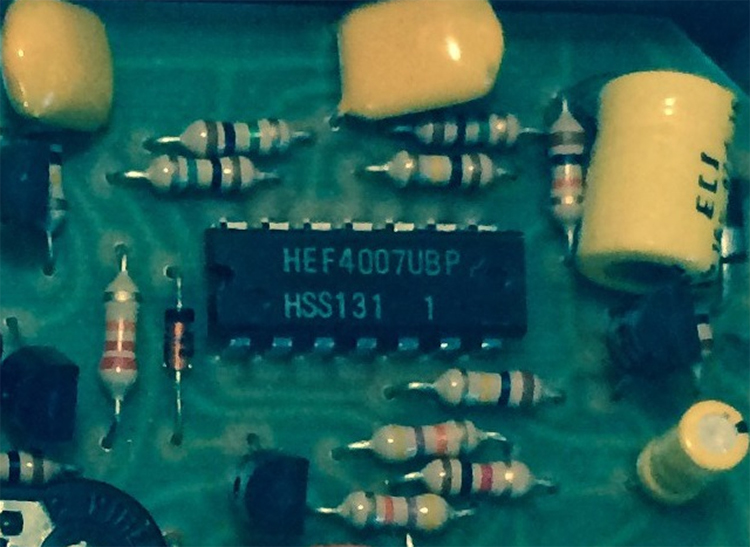
There are two types of components that belong to the TH category: axial and radial. Axial components have wire leads at each end. Radial, on the other hand, have wire leads that protrude from the bottom of the device.
These types of components are especially useful during testing and prototyping phases where manual adjustments and replacements are commonplace. Each type can be converted into the other by bending the leads to mimic the other’s form
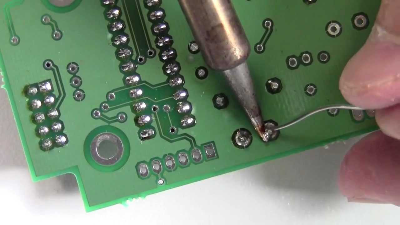
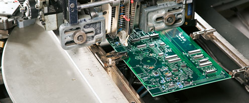
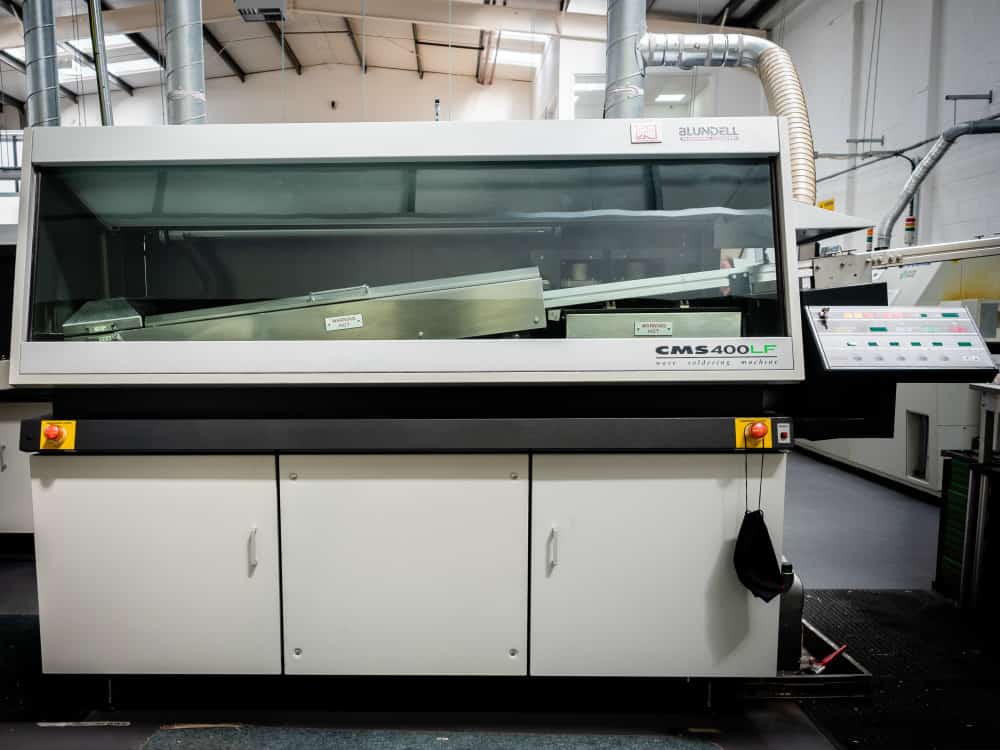
TH components can either be mounted manually or automatically with insertion mount machines. Both methods solder the two leads onto pads on opposite sides of the PCB. This process will then complete the circuit.
SMT has many reasons for overtaking TH, however, each method still has their pros and cons. Let’s take a look at TH’s pros and cons.
TH is the more convenient selection for hobbyists and engineers during the development stage since they are compatible with breadboard pin-holes and are easily swappable. The components and circuitry can be tested on breadboards before upgrading to a PCB. Although they eat away at tracing space below the top layer, engineers often prefer larger through holes while prototyping because of its ease of use with breadboards.
Through hole mounting (THM) also offers a certain amount of reliability when undergoing environmental stress. Threading components through the board increases the strength of the physical connections. They can withstand more strain than SMD and continue to operate efficiently. In fact, THM is widely used in aerospace and military products that require boards and components to endure accelerations, collisions, and extreme temperatures.
THM’s ability to withstand mechanical stress is also good for prototyping. And for those who must shell out hundreds of dollars on prototype boards, the relative affordability of TH components is a small win for engineers and makers. Sometimes you don’t even have a choice whether you use TH or SMD, as not every component you need comes in an SMD form.
However, there is a reason why SMT overtook TH technology—multiple reasons really. Unfortunately, as previously mentioned TH take up more board real-estate and requires drilling which can increase the costs of PCBs. Drilling can also increase the time needed to fab. Mounting TH components by hand is not as reliable as mounting SMT components, not an ideal situation for prototyping.
Compact, high-speed, and high-frequency designs have phased TH out of its heyday in favor of SMT which was designed to meet the fast-changing and highly demanding needs of technology. For many good reasons, SMT isn’t going anywhere, but then, neither is TH technology. For certain situations, there are more advantages than costs in choosing to use TH and TH components.
Do you try to avoid through-holes and their components at all costs or can you not get enough of them? Let us know in the comments below!
Smart Prototyping delivering you the best in prototyping services, components and equipment. View More
https://en.wikipedia.org/wiki/Through-hole_technology
https://www.smart-prototyping.com/blog/Through-Hole-What-and-Why
Sex Dolls Porno Video
Amateur Sex Party Tumblr
Black Boobs Anal
Through-hole technology - Wikipedia
What is a Through Hole and Why Should I Care?
THROUGH-HOLE | Definition of THROUGH-HOLE by …
Through-Hole | Universal Instruments Corporation
Through-Hole - Why It is Still Relevant in PCB Designs?
Hole - Wikipedia
Through Hole Soldering Process: A Guide for PCB …
through-hole mounting — с английского на русский
The Differences Between Through Hole and Surface …
SPDT Through Hole Ползунковые переключатели – …
Through Hole