Shell And Tube Heat Exchanger

👉🏻👉🏻👉🏻 ALL INFORMATION CLICK HERE 👈🏻👈🏻👈🏻
Возможно, сайт временно недоступен или перегружен запросами. Подождите некоторое время и попробуйте снова.
Если вы не можете загрузить ни одну страницу – проверьте настройки соединения с Интернетом.
Если ваш компьютер или сеть защищены межсетевым экраном или прокси-сервером – убедитесь, что Firefox разрешён выход в Интернет.
Время ожидания ответа от сервера en.wikipedia.org истекло.
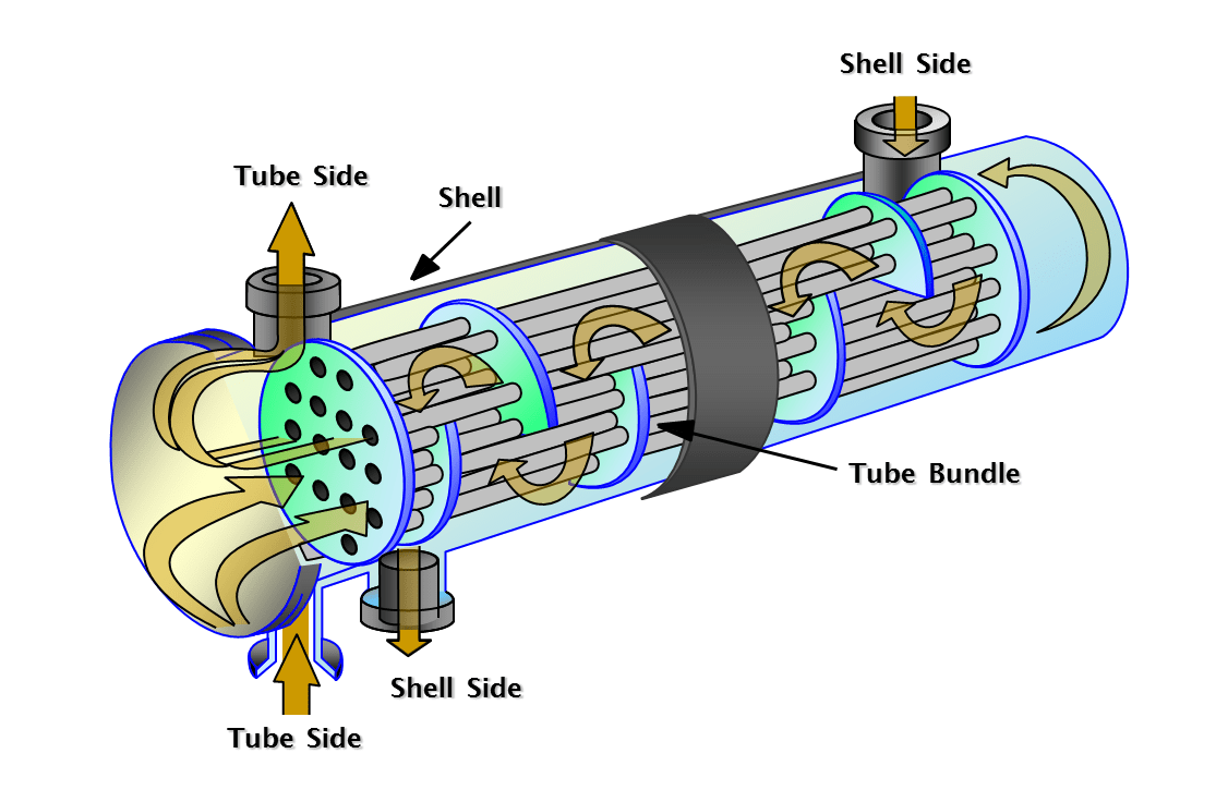
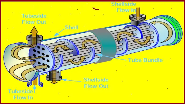
Fig. 1: Working principle of Typical Shell and Tube Heat Exchanger
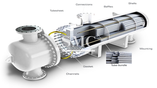
Fig. 2: Components of a Shell and Tube Heat Exchanger
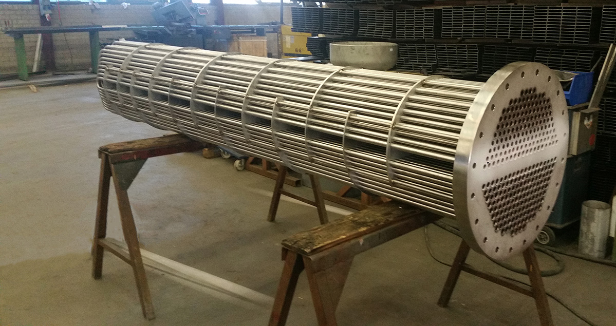
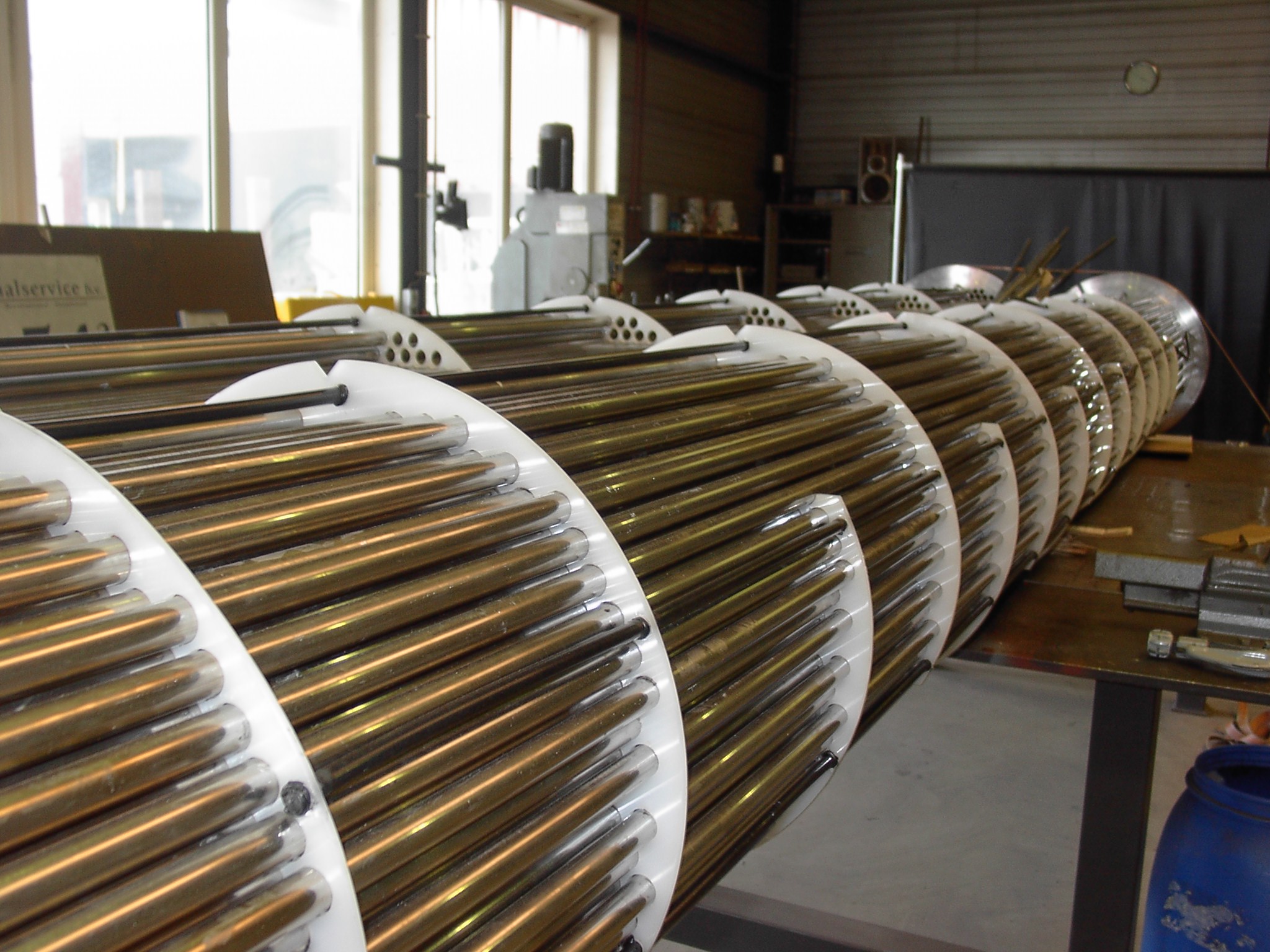
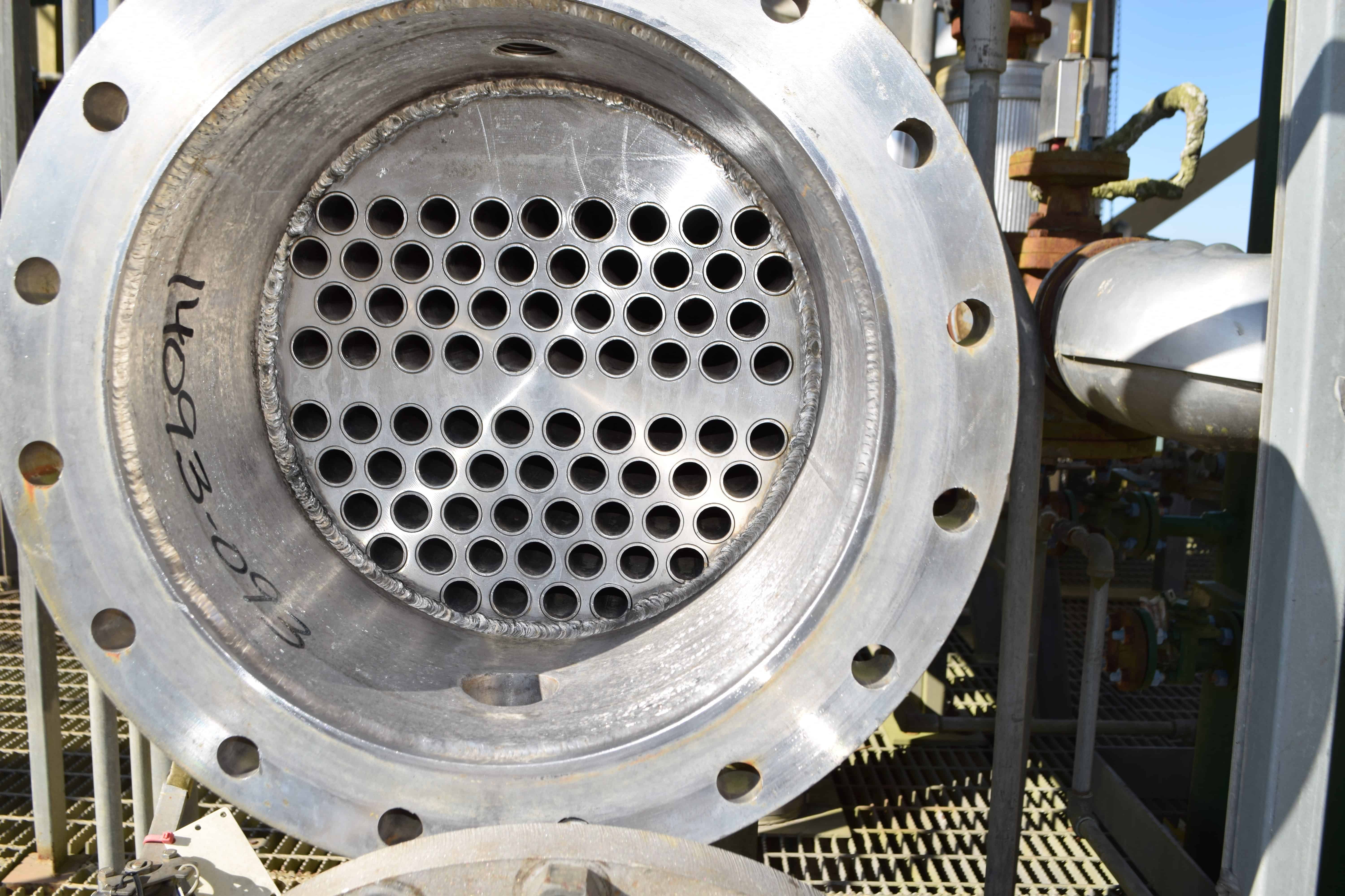
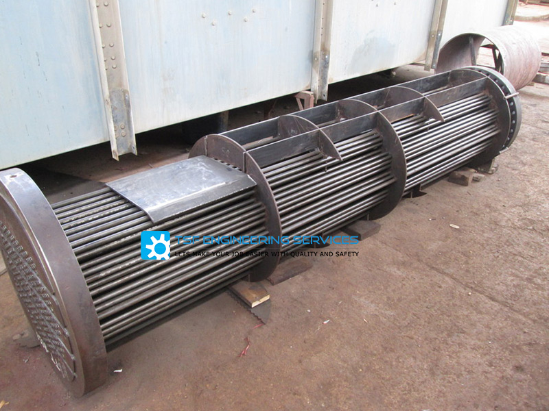
Fig. 3: Typical tube bundle of a shell and tube heat exchanger
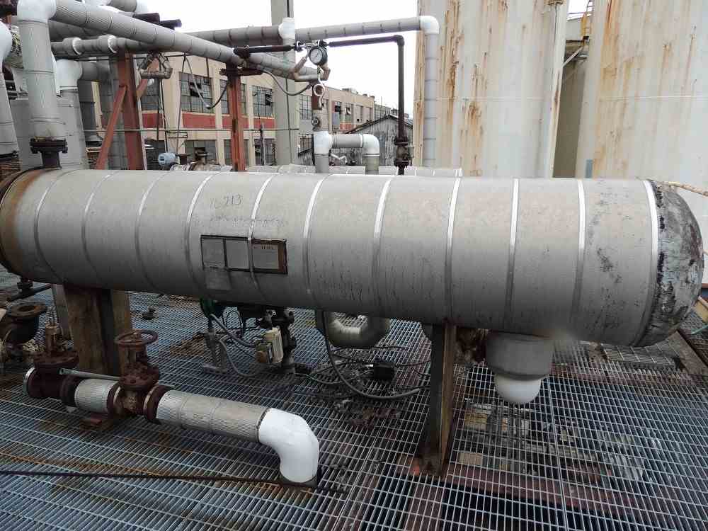
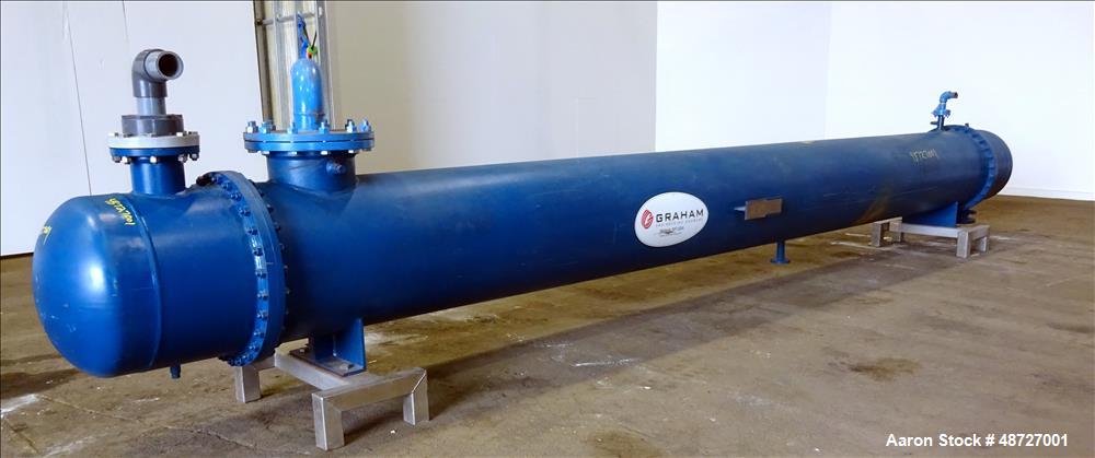
Fig. 5: Example of a typical fixed tube heat exchanger
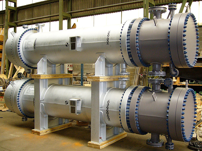
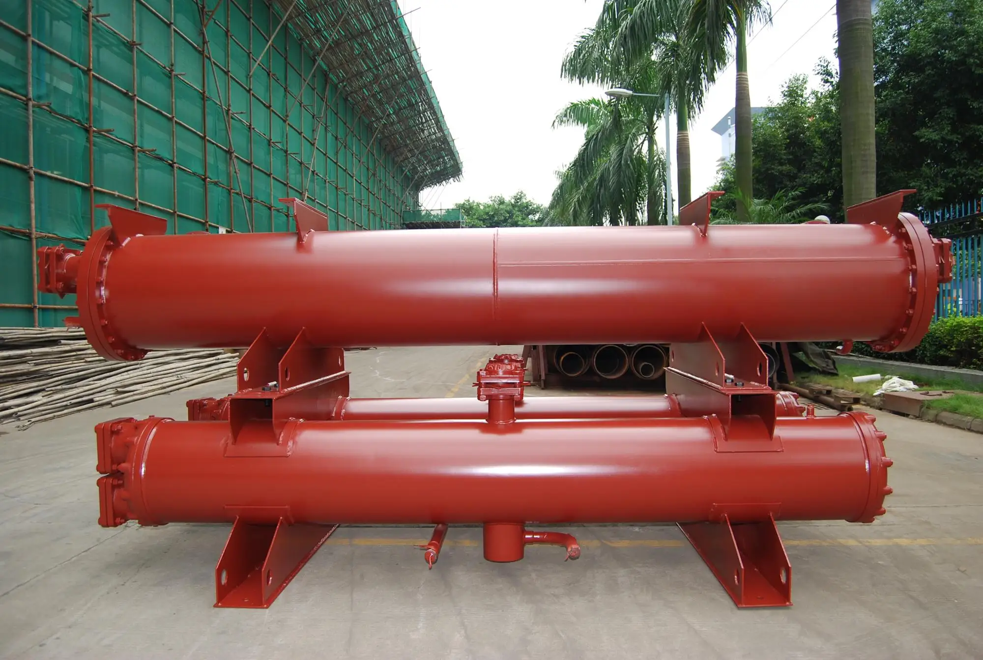
Fig. 6:Example of a typical Floating Head Removable bundle heat exchanger
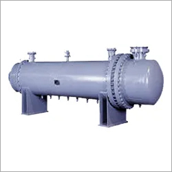
Fig. 7: Example of a typical stationary tube sheet type heat exchanger
Fig. 8: Typical representation of U-tube Heat exchanger
Fig. 9: TEMA Shell and Tube Heat Exchanger types
Fig. 10: Figure showing stack arrangement of heat exchangers
Fig. 11: Minimum Shell thickness of shell and tube heat exchanger
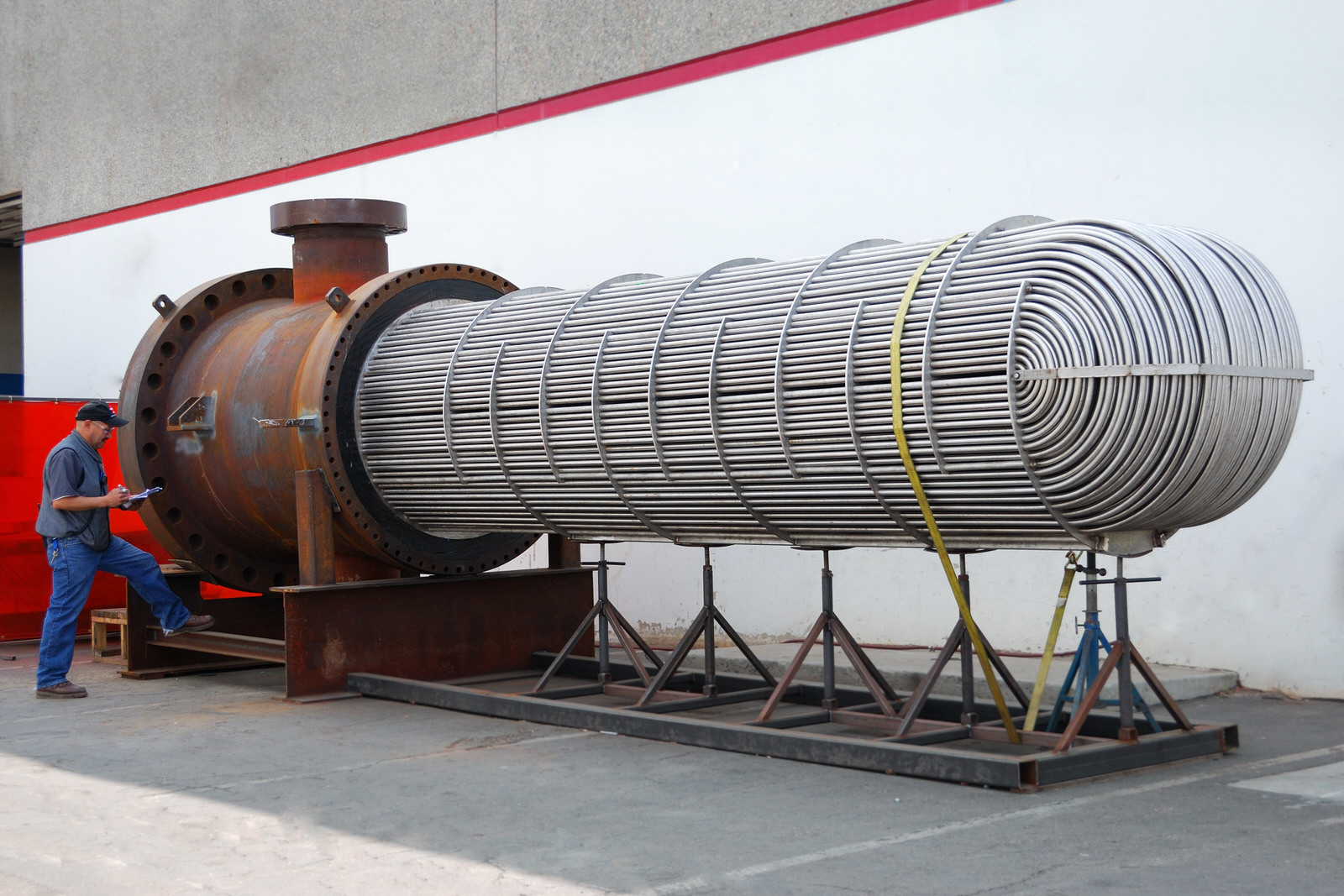
A Heat exchanger is a device to transfer heat from one fluid (Liquid/Gas) to another. There are various types of heat exchangers used in process piping. Shell and tube heat exchanger is the most widely used heat exchanger and are among the most effective means of heat exchange. Shell and tube heat exchanger is a device where two working fluids exchange heats by thermal contact using tubes housed within a cylindrical shell. The fluid temperature inside the shell and tube are different and this temperature difference is the driving force for temperature exchange. Used for wide temperature and pressure range, Shell and tube heat exchangers are compact in design, easy in construction and maintenance and provide excellent heat exchange.
As the name specified, it consists of a shell and a number of tubes. Shell is the housing of the exchanger and tubes are mounted inside the cylindrical shell.
The working of a shell and tube heat exchanger is fairly simple. One fluid flows inside the tubes and the other through the shell. While flowing they exchange the heats which means the cold fluid gains the heat from the hot fluid. So one cold fluid enters the shell (or tube side or channel side) inlet nozzle and comes out of the outlet nozzle as hot fluid. Obviously, the other fluid will become cold in the outlet than in the inlet. The heat transfer in a shell and tube heat exchanger is determined by the exposed surface area that is decided by the number of thermally conductive metal tubes. The fluid flow inside the shell and tube heat exchanger can be parallel flow or crossflow.
Fig 1 shows the typical working principle of a shell and tube heat exchanger.
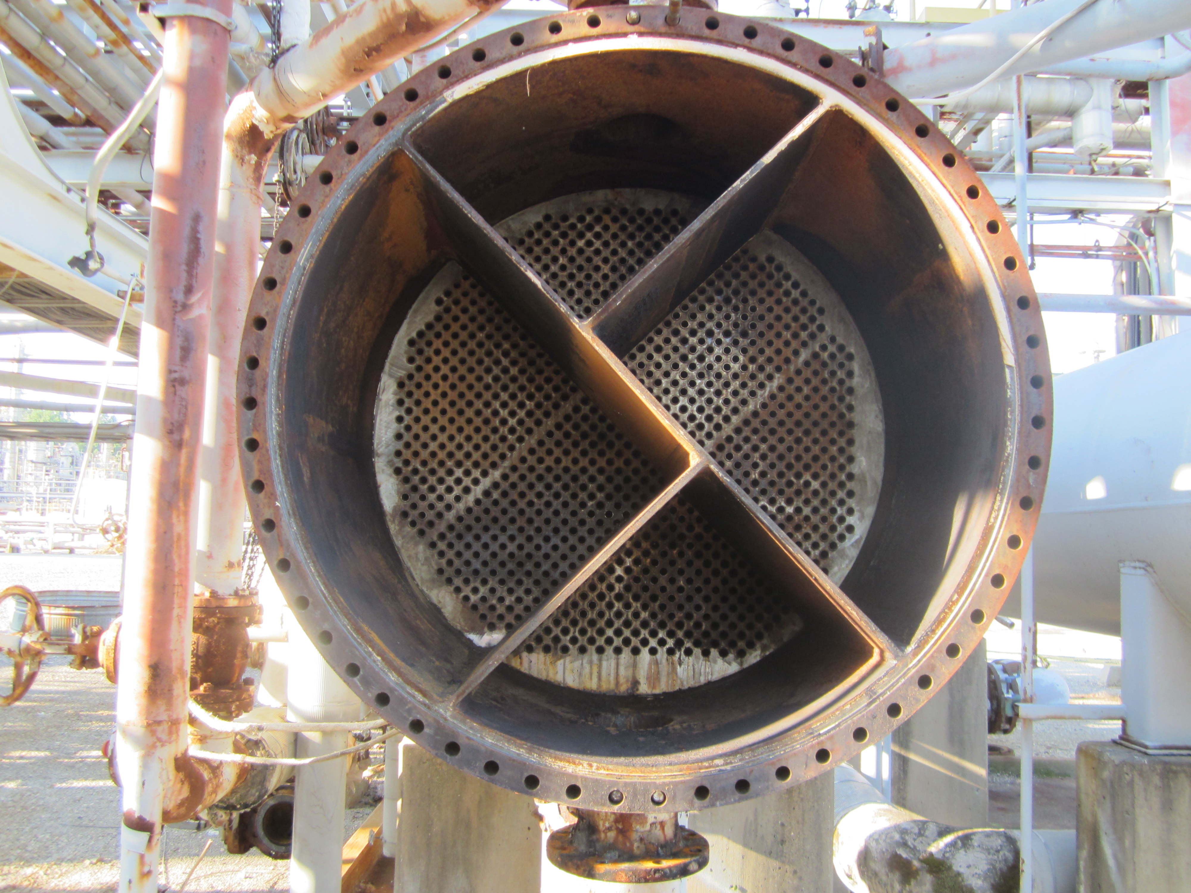
The above figure shows both inlet and outlet nozzle in the front header of the channel side. That means this exchanger consists of even number of tube passes. However, there can be odd number of tube passes. On that situation, the channel side outlet nozzle will be on the read header. Increasing the number of tube passes increase the heat transfer co-efficient.
To increase the fluid turbulence in the tube and shell side flow, turbulator and baffles are installed inside tubes and shells respectively. This increase the heat transfer between the fluids.
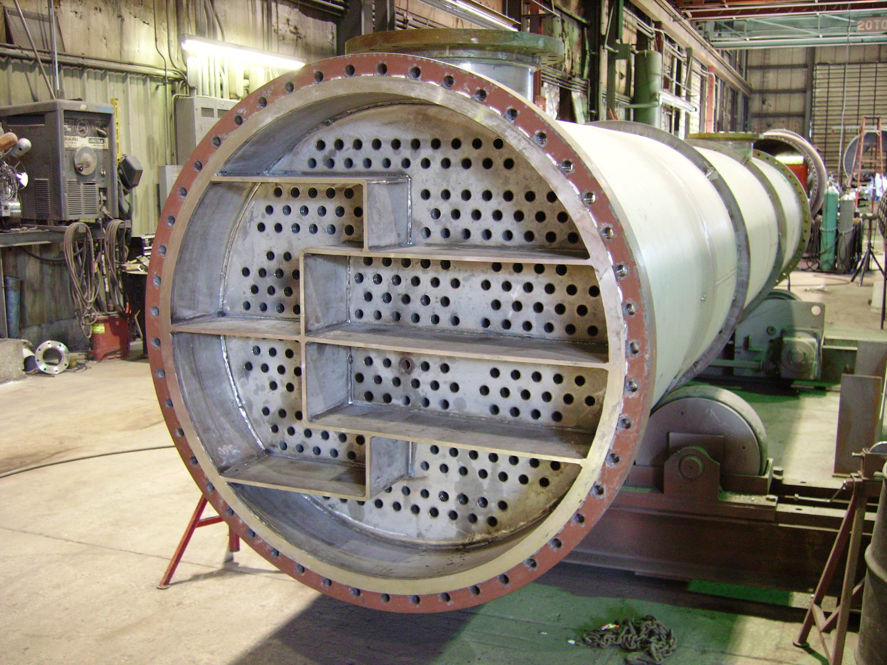
Typically a Shell and Tube Heat Exchanger consists of two-compartment / section one is shell side and other is channel/tube side
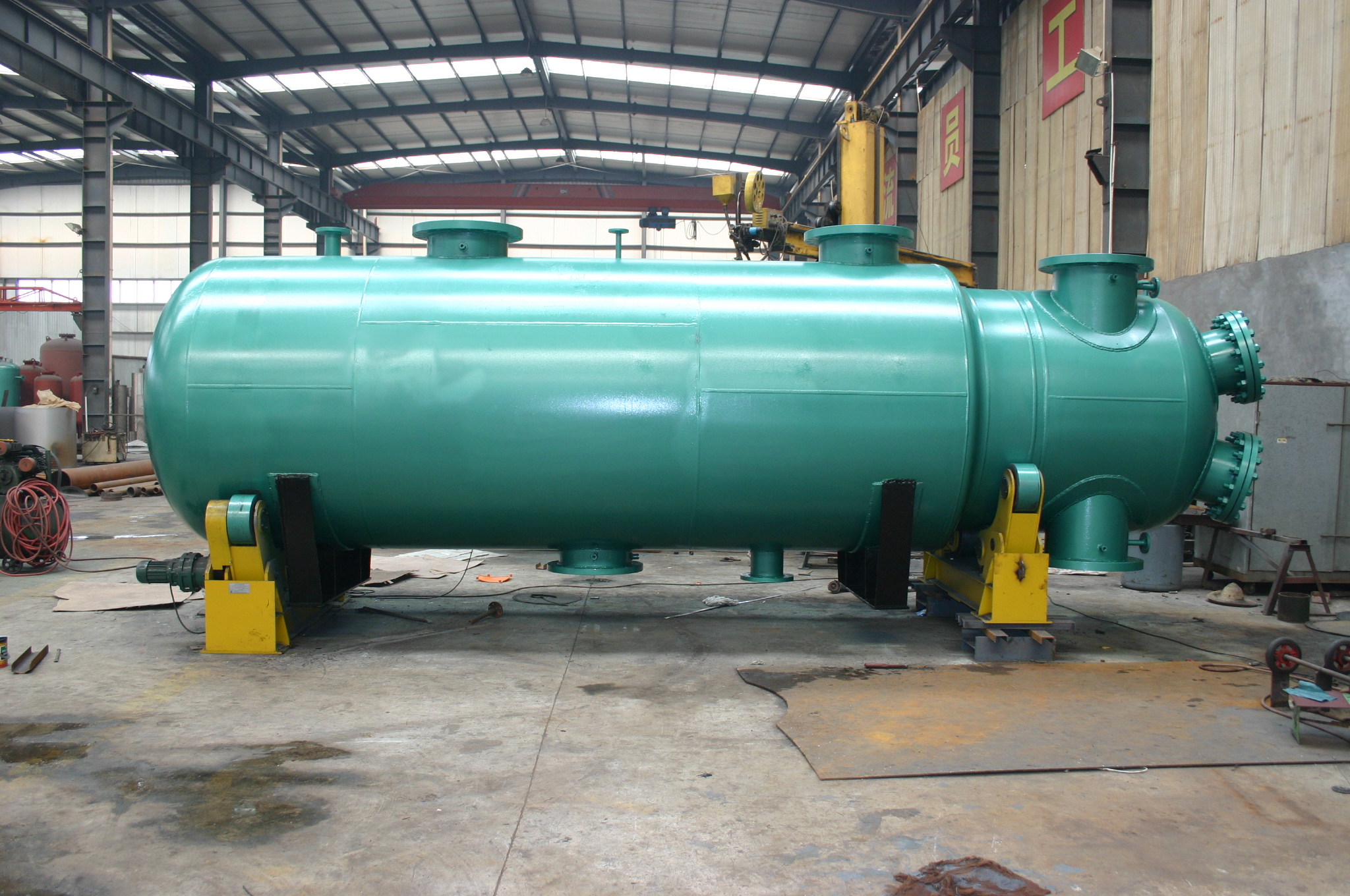
The heat exchanger is supported by saddles in the shell part.
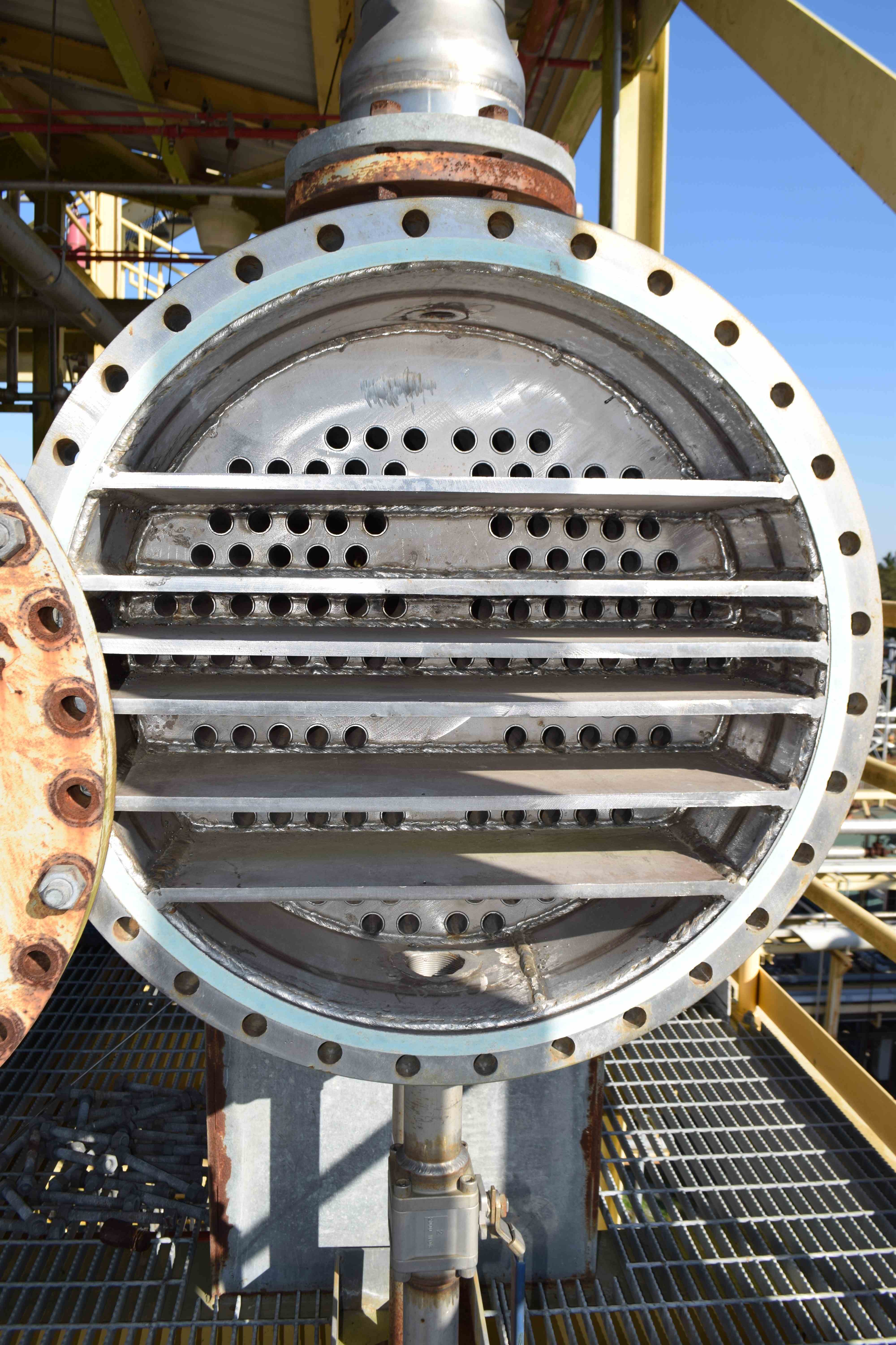
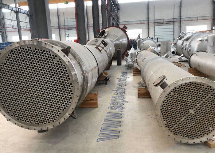
Tube Bundle (Fig. 3) consists of the following components
Tube bundles are removed during maintenance. Standard practice is to flow the corrosive fluid inside the tubes so that if corroded they can be easily replaced or repaired. Fig. 3 below shows a typical tube bundle.
Normally tubes inside the exchanger are of 0.5″ to 2″ in sizes and arranged in triangular or square pattern as shown in Fig. 4
The tube shall be placed with a minimum centre to centre distance of 1.25 times the tube outside diameter of the tube. When mechanical cleaning of the tube is specified then a minimum cleaning lane of 6.4 mm shall be provided.
Baffles are installed in the shell of the shell and tube heat exchanger to create more turbulence and increase the flow time so that better heat exchange is possible. Baffles support the tubes so that damage and vibration of tubes are minimized.
As per TEMA (Tubular Exchanger Manufacturers Association) Shell and Tube Heat Exchanger can be classified as
The reason behind such limitation is to keep the maximum shell wall thickness below 3 in. (76 mm), and the maximum stud diameter to below 4 in. (102 mm).
Depending on various construction and configuration parameters following types of shell and tube heat exchangers are widely used in industries.
The tubesheet is fixed in the shell by welding and hence the term fixed tube sheet exchanger applies. This simple and economical construction allows cleaning of the tube bores by mechanical or chemical means. An expansion bellow is installed in the shell when there is a large temperature differences between the shell and tube materials. Refer to Fig. 5 for an example of fixed tube heat exchanger.
In floating head construction, the rear header can float or move as it is not welded to the shell. The tube bundle can easily be removed while maintenance. Fig. 6 shows an example of floating head heat exchanger.
Fig. 7 shows an example of stationary tube sheet with removable tube bundle.
U-tube exchangers are a type of shell and tube heat exchanger whose tube bundle is made of continuous tubes bent into a “U” shape. The bend side is free-floating and this helps in thermal expansion without requiring expansion joints. However, such bends are difficult to clean.
Based on the number of times the tube-side/shell-side flows pass through the exchanger, shell and tube heat exchanger is categorized as:
The full TEMA classification of shell and tube heat exchanger types are provided in Fig. 9 below:
Depending on the application of shell and tube heat exchangers, they are known as various types as listed below:
In this, two or three heat exchangers placed one above other. This is termed as 1 shell in parallel and 2 or 3 Shells in series. Refer Fig. 10.
The following codes and standards govern the design of shell and tube heat exchanger.
Design of Shell and tube heat exchanger is a trial and error iterative process. In recent time, the thermal design is carried out by the process team using engineering software. However, the logic behind the calculations should be clearly understood. The shell and tube heat exchanger design calculations are based on initial selection of a preliminary exchanger configuration and certain initial decisions like
Further steps for the shell and tube heat exchanger design consist of
Once the requirements are met, a process datasheet is developed indicating all process design parameters of shell and tube heat exchanger design.
The following table (Table-1) provides general guidelines for shell and tube side fluid allocation in a shell and tube heat exchanger:
High fluid velocities increases heat transfer coefficients and reduces fouling but causes erosion and increases pressure drop. So velocity selected should be just enough to prevent settling of suspended soilds. Typical fluid velocities considered for the design of shell and tube heat exchangers are given the following table (Table-2):
Typical pressure drop values considered for shell and tube heat exchanger design are:
The most popular software used for thermal design of shell and tube heat exchanger are listed below
Mechanical design of shell and tube heat exchangers consist of calculation of shell thickness, flange thickness, etc. Various codes like ASME Sec VIII, PD 5500, TEMA, etc provides guidelines for mechanical design. The following design guidelines can be followed:
Following materials are the most common as Shell & Tube Heat Exchanger MOC.
Depending on user experience and manufacturer guidelines, shell and tube heat exchangers should be inspected at regular intervals. A shell and tube heat exchanger can fail by one or more of the following factors:
Following preventive maintenance steps at regular intervals can reduce the risk of equipment failure. Following maintenance steps can be followed to enhance shell and tube heat exchanger performance:
Shell & Tube Heat Exchangers find their application in the following Industries-
I am a Mechanical Engineer turned into a Piping Engineer. Currently, I work in a reputed MNC as a Senior Piping Stress Engineer. I am very much passionate about blogging and always tried to do unique things. This website is my first venture into the world of blogging with the aim of connecting with other piping engineers around the world.
Need some focus on expansion bellows.
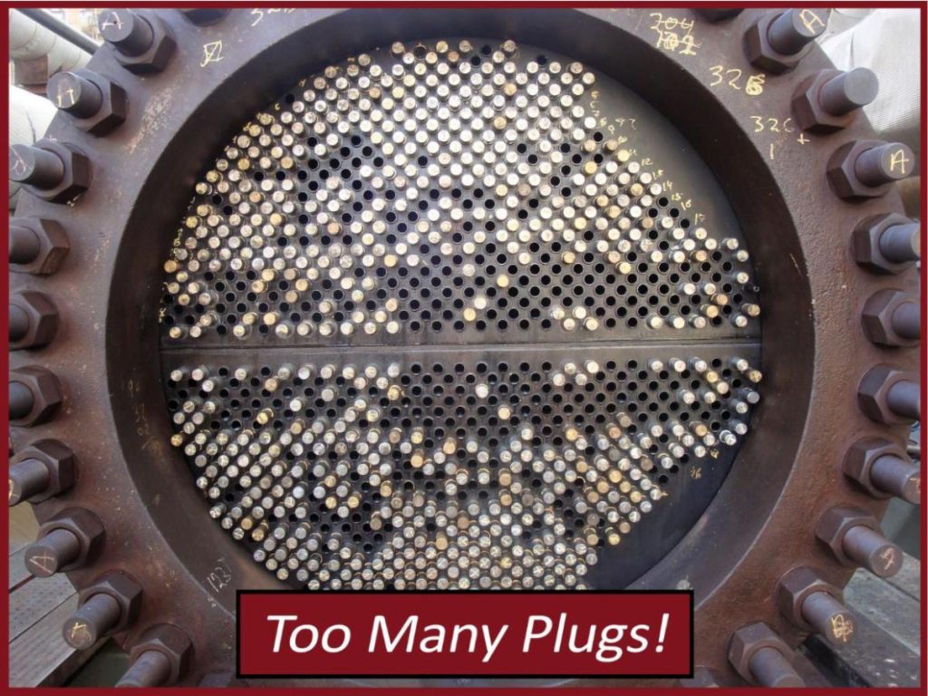
What I like the most about the shell & tube design compare to other type like plate and frame or helicoil is that despite the fact they are built to last for a longer life is: 1- The tube bundle is easy to replace because you have just one or 2 gaskets to replace 2- They are easy to repair a tube temporary by plugging it for a fast restart of the process while waiting for the next shut down 3- If you need to clean the tubes, you can easily see from your eyes if the tubes are clean enough. 4- For high scale application their is the possibilty to add an automatic brush in each tube to avoid any scale or plug tube.
In steam application I suggest to use a vertical shell & tube design to flood the heat exchanger.
Congratulations Great presentation with very easy explanation to understand the fundamentals of heat exchanger Thank you
Very good presentation and very Informative.
Very Nice Presentation. Can we see any operation and maintenance guide for Shell & Tube type heat exchanger
Congratulations Very good prasentation .sir ..
Thanks for a detailed information. Requesting you to also describe details related to its piping arrangement. Guidelines to be taken if the heat exchanger is located on the ground or on platforms above.
Congratulations.. Good presentation Sir
Congratulations sir and very good presentation of Heat exchanger
Hi Anup. Very Good presentation. Do you have a presentation on maintenance of shell tube heat exchangers?
I would like to strengthen aspects such as: – Recommended gaskets for service – recommended torque and / or tensioning – Hydrostatic tests on high pressure equipment on both sides.
API 660, API 572 and ASME PCC-2 offer help, however I would like to know your opinion.
Congratulations Good presentation thanks
Your email address will not be published. Required fields are marked *
Save my name and email in this browser for the next time I comment.
Coalescer is a piece of important industrial equipment for the oil and gas industry used for liquid-liquid or liquid-gas separation from hydrocarbons. A coalescer uses its baffles or electric current...
Reboiler Control is very effective to a distillation column as it prevents the distillation column from disturbances occurring in the heating medium. Reboiler controls include reboiler temperature...
Hi There! Welcome to my space, I am Anup Kumar Dey, an experienced piping engineer from the last 15 years. Through this platform, I will share my experiences and knowledge with you in an innovative way. So be with me for the next couple of years!
Fluid with low heat transfer co-efficient
https://en.wikipedia.org/wiki/Shell_and_tube_heat_exchanger
https://whatispiping.com/shell-and-tube-heat-exchangers/
Forced 3d Porn
Erotic Pantyhose Film Adult
This Account Is Private Instagram
Shell and tube heat exchanger - Wikipedia
Basics of Shell and Tube Heat Exchangers (With PDF) – What ...
All About Shell And Tube Heat Exchangers - What You Need ...
5.1 Shell-and-Tube Heat Exchangers - Homepages at WMU
SHELL AND TUBE HEAT EXCHANGERS - thermopedia.com
Shell & Tube Heat Exchangers | Armstrong Fluid Technology
DESIGN OF SHELL AND TUBE HEAT EXCHANGER - EPCM Holdings
Alfa Laval - Shell-and-tube heat exchangers
Shell-and-Tube Heat Exchangers | McMaster-Carr
Shell And Tube Heat Exchanger