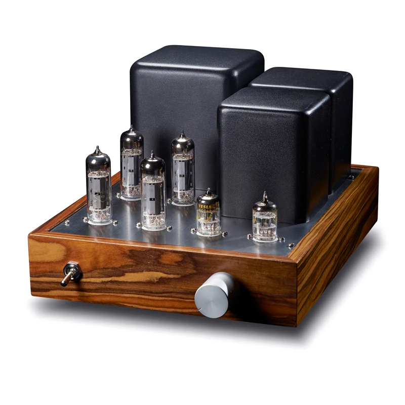
Pp Tube Amplifier

💣 👉🏻👉🏻👉🏻 ALL INFORMATION CLICK HERE 👈🏻👈🏻👈🏻
Возможно, сайт временно недоступен или перегружен запросами. Подождите некоторое время и попробуйте снова.
Если вы не можете загрузить ни одну страницу – проверьте настройки соединения с Интернетом.
Если ваш компьютер или сеть защищены межсетевым экраном или прокси-сервером – убедитесь, что Firefox разрешён выход в Интернет.
Время ожидания ответа от сервера next-tube.com истекло.
HOME
STORE
BLOG
SCHEMATICS
TUTORIALS
DOWNLOADS
CONTACT
The previous project, the OddWatt 225 (6SL7 SRPP / KT77 Class-A Push-Pull Tube Amplifier) is in daily operation and (with JJ KT77 tubes) has a wonderful tube sound. The Odd Blocks are rather similar only they are two separate amps and were planned up front to be able to use any of the power tubes that share the same pin arrangements (6L6GC, KT77, KT88, EL34, 6CA7 and all the variants). TubeDepot.com has a good selection of these tubes - NOS and new productions. I initially used KT77 tubes as I was familiar with the sound and it would be a good starting point. I tried the amp with Electro-Harmonix KT88 tubes. Using the EH KT88 tubes has been a mixed situation. The EH KT88 can deliver more power, but the sound is different from the KT77. Additionally they don't behave well in this particular amp. I suspect the reason is related to thermal problems and the use of common (joint) cathode bias. The circuit allows for adjustment of the bias (the 25 ohm variable resistor) but the EH tubes do not stay in sync. One or the other tube (not predictable which one) will start to conduct more than its fair share of the current. With current balance being an important consideration of the design this is not good. By comparison the JJ 6L6GC tubes and JJ KT77 will balance within one mA and stay there. It is possible that this is a situation with just the one brand of KT88s. I have since then acquired a set of new production Gold Lion KT88 tubes and they behave perfectly. I will not further speculate why the one brand works and the other doesn't. It is just the way things are. For a more complete description of how the two stages of the amp work see the original OddWatt project (ECC802S SRPP / EL84 (6BQ5) Push-Pull Tube Amplifier). The SRPP driver and SIPP output work very well together. An alternative driver for 9 pin application is the type 5751. This tube will directly substitute for the octal 12SL7 in this circuit. Other tubes with the same base as the 5751 (12AU7, 12AT7 and 12AX7) were tried, but none performed as well as the 5751.
6NO30 Thermal Delay Relay Vacuum Tube
Photograph 2: 6NO30 Thermal Delay Relay Tube
As in nearly all tube projects dangerous voltages are used. Contact with the voltages at various points in this circuit can be fatal. If you are not familiar with tube equipment or are not experienced with high voltages, perhaps this is not a suitable project.
This is a pair of mono blocks amplifiers - each with its own power supply. In some ways this is more complex and costly and in some ways cheaper, easier and has advantages. For starters if you only need one amp, then you need only build one. Second if you need three (perhaps one for a sub woofer) then you can build three. In the stereo version it requires two power transformers, rectifiers and filters. But the transformers are less expensive than the one needed for a single chassis stereo amplifier. A side benefit is that you don't need a set of wheels to move the amps. A single chassis amplifier would weigh in excess of 50 pounds.
SRPP / SIPP Tube Amplifier Design with CCS
For design purposes I found that potential power tubes pretty much fell into two groups. Group "A" consists of KT77, 6CA7, EL34, 6L6GC and similar variants. Group "B" consists of KT88, KT90, 6550 and their variants. The difference is in both the bias voltages and maximum power dissipations. In the measurements and listening sections I relate the differences. The basic circuit is the same as previous Oddwatt amplifiers (see other projects). I saw no reason to mess up a good thing. There are some refinements though. The CCS in the original amps was a standard LM317 voltage regulator IC. I have since switched to the LM317HV. The voltage breakdown margin is better. I understand that these are discontinued but there are many available in parts houses. It really is only needed for the "B" version. The "A" version can use the standard LM317. To date I have not been informed of any failures in either application, but I don't feel comfortable with the 37 volt rating of the standard parts in the KT88 application. Some resistor values in the SRPP stage have been changed to increase in the current flow. Other DIYers have determined that this reduces the distortion level a bit. It makes sense, but measurements to date have not confirmed it as the level was already quite low. The power supply uses a Edcor 180-0-180 transformer with a full wave bridge across the full winding. With capacitor input filtering the B+ is between 450V and 475V. I tried a one Henry choke for a filter and decided it wasn't worth the cost and failed to significantly improve the filtering.
12SL7 SRPP KT88 Push-Pull Tube Amp Schematic
Figure 1: OddBlocks - 12SL7 SRPP / KT88 Push-Pull Tube Amp Schematic
12SL7 / KT88 Tube Amp Power Supply Schematic
Figure 2: OddBlocks - Power Supply Schematic
Part of DIY is that you can do things that manufacturers won't. I found a source for 6NO30 "tubes". For those of you who don't recognize it, this is a thermal relay in an octal socket. This is a rather old technology gizmo. It is the same size and shape as the 12SL7 and thus adds a nice symmetry to the amps. These "tubes" work on the principle of a heating element and bi-metal switch. The contacts are rated for 500,000 operations at full power. Unfortunately the voltage rating of the contacts is 120 VAC (breakdown voltage rating is 500 volts when new - whatever that means). Clearly, this is not high enough for the 360 volts AC being switched. So I use the contacts to activate a 12 volt relay that actually does the work of connecting the AC (360 v) to the rectifiers. The 6NO30 delays the activation by 30 seconds. Other values of thermal relays are available as well. These were cheap ($2.96 each) NOS. The numbering for them is as follows: The first digit(s) is the heater voltage. Then follows either NO or NC, for Normally Open or Normally Closed for the internal contacts. Finally the last numbers indicate the seconds of delay. Using the thermal relay is probably a sign of madness and the job could be done simpler with a transistor and a few passive parts, but it sure is cool. The remainder of the PS is similar to my other projects. I use a generic, inexpensive 12 volt, 3 amp SMPS to power heaters as it is cheap, very compact and provides clean well regulated power. A conventional transformer, rectifier, and filter could be used. The windings on the Edcor power transformer are 6 volts and would be satisfactory for group "A" tubes. For group "B" tubes as bigger transformer is needed. Generally, it is a bit easier (and cheaper) to get the required power at 12 volts at 2 amps than at 6 volts and 4 amps. Losses are lower for one. AC could be used on the heaters as well. It would most likely increase the noise floor a bit. If you are at all like me, you hate hum and noise. I would stick to SMPS for the heaters in all but "budget" builds of these amplifiers.
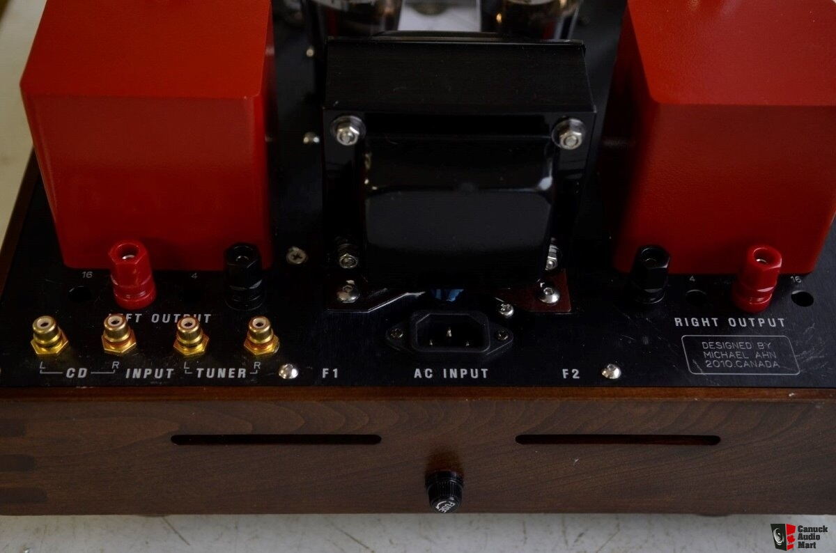
Construction - OddBlocks Tube Amplifier
The build is pretty straight forward. The chassis is steel by Hammond purchased from Antique Electronic Supply. The transformers came from Edcor. Wiring was point to point and I used some terminal (aka turret boards) boards for connections. The more sensitive circuitry is placed as far from the power transformer and noise sources as possible. The filter capacitors and B+ relay were glued to the chassis. A significant feature is the use of a ground buss (seen as a large bare copper wire in the photos). This has worked well in the past projects for minimizing hum, noise and the possibility of ground loops. A special precaution is required with regard to the heater circuits. I discovered some time ago that it is easy to exceed the heater to cathode voltage ratings of the driver tube when you use a SRPP design. There are several possible solutions. The one I used is to bias the heaters at about one third of the 240 volt supply. There is no current flow (just a tiny bit of leakage - in the microampere range). There are two extremely important considerations with this method. One, no part of the heater circuit can be grounded. Second, the source of the heater power must also not be ground referenced. It needs to float sort of like the heater circuit for many tube rectifiers. If you use a SMPS it needs to have the output isolated from the input and not in any way referenced to the ground. If it is not, then failure is virtually guaranteed. Another important point in the construction is the connections to the CCS. The "adjust" terminal of the LM317HV is grounded. The sense resistor is between the output terminal and ground. This is different from the use of the IC as a voltage regulator. When properly connected, the current is equal to 1.25 divided by the value of the resistor in ohms. Thus 10 ohms will result in a 0.125 amp current flow. The CCS needs to be heat sinked as it has to handle up to 8 watts of dissipation (when using KT88 at 180ma - less for other tubes and currents). Now for some magic, if you use a fixed 10 ohm resistor in the CCS for a basic setting it will result in close to 62 mA per tube. If you have a 22 ohm resistor connected in parallel to it with a simple SPST switch you can bump up the current to 90 mA per tube. The first setting is perfect for group "A" tubes and the second for group "B". Tube swapping is very easy in this amplifier.
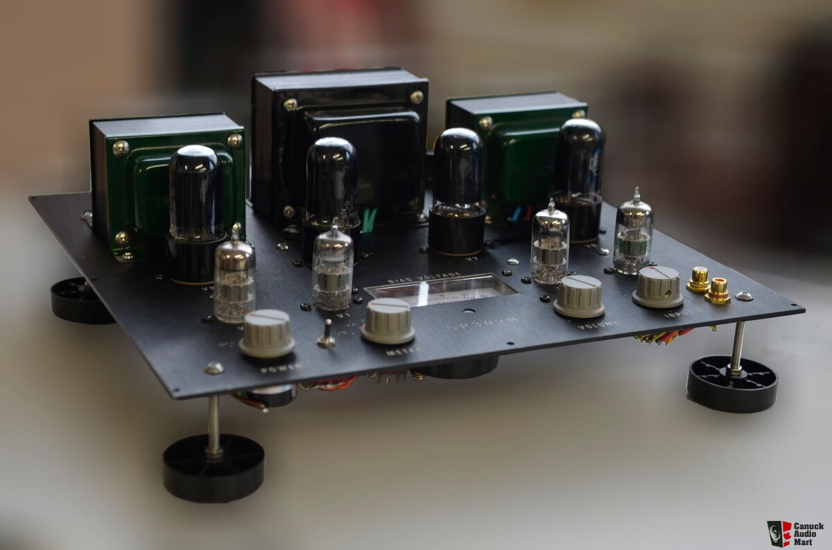
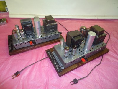
12SL7 SRPP / KT88 Push-Pull DIY Tube Amplifier
Photograph 3: 12SL7 SRPP / KT88 Push-Pull Tube Amplifier - Inside View
For additional tube amplifier design and construction tips, see my design and construction tips and suggestions for vacuum tube amplifiers. Also, I have posted some suggestions for a tube amplifier wiring color code that you can use during construction.
Testing and Operation
Before actual listening to the amp it is important to verify that heater and B+ supplies are operational. There are lethal voltages in this amp, use extreme care when making any measurements. I suggest that you install the 6NO30 (if you use one) and not any of the other tubes. Turn on the power and check the voltages. There should be 12 VDC between the heater pins on the 12SL7 socket and B+ around 475 at the filter capacitors. The 240 voltage point will be high (close to the 475 reading) as there is no load on the circuitry. There should be no B+ until the 6NO30 switches (about 30 seconds). If all is well, shut the power off. The filters will be fully charged at this point so be careful not to contact any part of the circuitry. Insert the remaining tubes and reapply the power. Watch for problems (tube plates glowing red, sparks, smoke, noises and other fun things that indicate bad news). Check the voltages again. They should be in the proper ranges (12 VDC on the heaters, B+ of 475 and 240). If they are greatly different, something is wired wrong. If all is OK, shut down the power and attach speakers. Turn on the power. There should be little or no sound (hum or noise) coming from the speakers. A small amount may be OK if you have very sensitive speakers. If you can hear it at 12 inches from the speaker, then there is probably a ground / shielding type of problem. I have 93 dB/watt speakers and the hum and noise is barely audible with your ear directly on the speaker grill. If this all checks out, then feed the amps a signal and see what comes out. It should be warm sweet tube music. Now is the time to do an initial balance on the output tubes. A volt meter across the test points should read in the 40-200 mV range. The object is to adjust the control to make the reading for each tube the same. The readings should add up to a number equal to the mA that the CCS is set for. If you selected 125 mA, then the sum of the two readings should be close to 125. It is not important to be exact at this time. Allow the amp to run for at least 15 minutes and check the setting again. It will probably have changed a little - so reset it. I suggest that you check it this way about once a month to account for tube ageing. If the tubes won't balance then swap them. Some tubes are more sensitive to having the grid on the ground than others. It is nearly always possible to get them to balance. If the tubes won't balance then there is probably either a wiring error or a tube that is out of tolerance. It is not necessary to have matched tubes, but if the price is right then it makes them closer and easier to balance. I have found that not all companies balance tubes the same way and sometimes "matched" sets don't work as well as randomly selected ones. This circuit balances them at a fairly high level of idle current. Many companies use a small current value or base the tests on maximum voltage and current. For what it is worth, I have had good luck with JJ tubes and not so good experience with EH KT88 tubes. Just to be sure no one gets too excited, it may not be EH's fault. Not all tubes work well in all circuits and the EH KT88 tubes may be just fine in other designs. The ones I have just don't work well in this instance. The Gold Lion KT88 tubes worked fine, so it is not a basic property of the KT88 tube design itself.
One area that always seems to cause problems is the phase of the feedback loop. In one orientation it will be "negative" and in the other it will be "positive". Negative feedback stabilizes the gain and response of the amplifier. Only a small amount is used. It also takes care of any possibility that something will excite the output transformer resonances at around 60 kHz. Positive feedback will do just the opposite. The easiest way to tell without test equipment is to listen. If the feedback is negative the output will be a bit lower than if it is disconnected. If the output is louder is positive. This is easy to see on a scope when you feed in a small signal. With the small amount used it will be just slightly lower in volume (about 3-6 dB). I received word from another DIYer who used different output transformers. His high frequency response was down quite a bit. In this instance, I suggest trying lower values of the NFB capacitor (1000 pF). The exact values for the resistor and capacitor are based on the Edcor transformers. If you use some other brand you may have to experiment with the values.
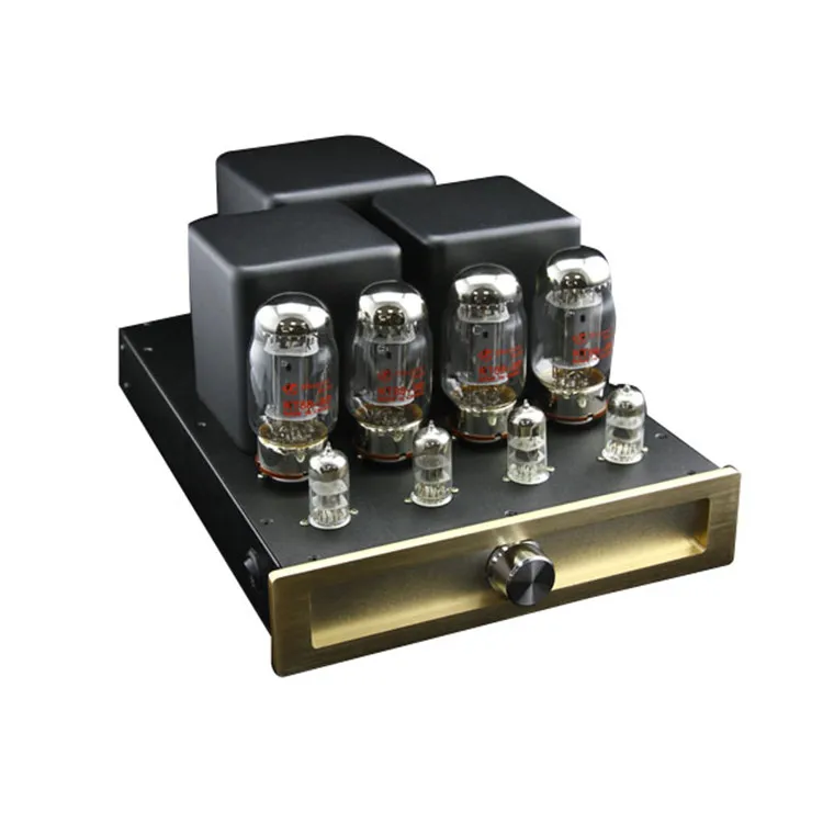
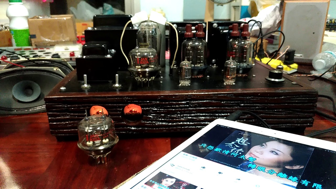
12SL7 SRPP / KT88 Push-Pull DIY Tube Amplifier
Photograph 4: Odd Block Tube Amp with Cover Removed
Measurements - Push-Pull KT88 Tube Amplifier (12SL7 Driver)
Measurements were made using a HP 331A distortion analyzer, Tenma Low Distortion Signal Generator (0.05% residual THD)and a Velleman PCSU1000 (PC interface) oscilloscope. The results from testing the amplifiers are quite similar to the results from the OddWatt 225 (6SL7 SRPP / KT77 Class-A Push-Pull Tube Amplifier). That is not really a surprise as they are rather similar. With an 8 ohm resistive load the response measured from 8 Hz (the lowest I can generate) to 19 kHz (at -1 dB). The minus 3 dB point was 30 kHz. The Gold Lion KT88 tubes were up +0.5 dB at 10 Hz while the JJ KT77 tubes were flat at that frequency. Distortion was 0.14% or less at one Watt (see later comment) throughout the whole frequency range. For group "A" tubes output before distortion was seen on the oscilloscope was 15 Watts depending on the specific tubes used. Up to 20 Watts were possible. With group "B" tubes the corresponding output was 24 Watts and around 30 with noticeable distortion. As expected the distortion was virtually all harmonics. Typically they were suppressed by around 50 dB. Hum and noise were below -74 dBV which is the noise floor of my present test set up. It was virtually all wide band noise. At one Watt, the distortion harmonics were buried in the noise floor. For those of you who are graphically inclined, I included a spectrum analyzer shot of a 1000 Hz sine wave and a few square wave images. I only included square wave response images as the sine wave ones were perfect copies of the input signal at all frequencies. When I wanted to run a full distortion profile I ran into a problem. Just before I started I discovered noise on the AC mains in my shop. The noise tended to confuse the HP analyzer. The initial results were below the 0.15 % range and until I can clear up the noise problem I don't want to make any additional claims. In its place I ran a bunch of high power scope tests. The KT88 version was able to deliver 24 watts of square waves from 20 Hz to past 10 kHz. They looked a lot like the ones at one Watt.
This is as I have noted on several occasions a difficult to address topic. What I hear and like is almost certainly different from what someone else hears and likes. I like to be involved in the music. If anything sticks out, it will degrade the experience. So I tend to like smooth response, lots of detail, wide soundstage and full spectrum of sound. These amps deliver all that in quantity. Regardless of what tubes I used for outputs, the sound is "silky" and refined. At the same time it has a very solid bottom end. This is nearly good enough for me to turn off the subs. Yes I admit to using subs. Two huge 7 cubic footers with 15 inch drivers. They are powered by a DIY LM3875 non-inverting chip amplifier (gainclone) kit and the signal is separated by a 24 dB/octave Marchand electronic crossover at 50 Hz. The main speakers are a pair of modified Altec Lansing 1010. The sound using just the mains (full range with no crossover to subs) is full and solid. There is plenty of bass for anyone but someone like me. I love those bottom two octaves. Imaging is excellent, very stable centering, separation is limited only by the other equipment (they are mono blocks after all), detail is excellent, and the sound has that quality of warmth that you would expect from a tube amp. My personal feeling is that the JJ KT77 tubes have the most refined sound while the JJ 6L6GC and the Gold Lion KT88 tubes have the best bass. The KT88 tubes are of course louder.
After Thoughts
I always have ideas after the project is done and working. For instance is it easy to build? As a DIY project with point to point wiring, it is not particularly easy for a novice. For a more advanced builder, it would be easy. This is not the best choice for a first project. Is it worth the cost and trouble? I think so. The transformers and tubes are the main expenses. They will run about $150US for each channel. The re
https://next-tube.com/articles/Veen2/Veen2EN.pdf
http://electronics-diy.com/class-a-push-pull-tube-power-amplifier.php
Whore Warcraft
Classy Nylons Adult Photo Magazine
Dp Porn Vk
NEW PUSH-PULL TUBE AMPLIFIERS
Class-A Push-Pull Tube Power Amplifier - Electronics DIY
Push-Pull (PP) EL84 Tube Amplifier Schematic (ECC83 input)
EL34 Push-Pull Mono-Block Power Amplifiers - Tube-Amps.net
Baby Huey PP EL84 amplifier - diyAudio
Power Amplifier – K & K Audio
PP2012 - KT88 Hi-End Push Pull Amplifier
Stereo 20PP Integrated Amplifier - Stereo 20 PP ...
The Most Popular High-End Tube Amps | Top Tube Amplifier
The 2A3 Tube Amplifier - A Tribute to Simplicity and Warm ...
Pp Tube Amplifier