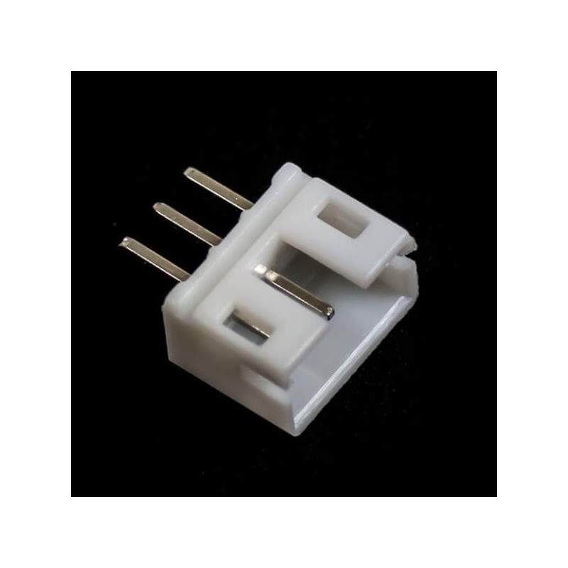
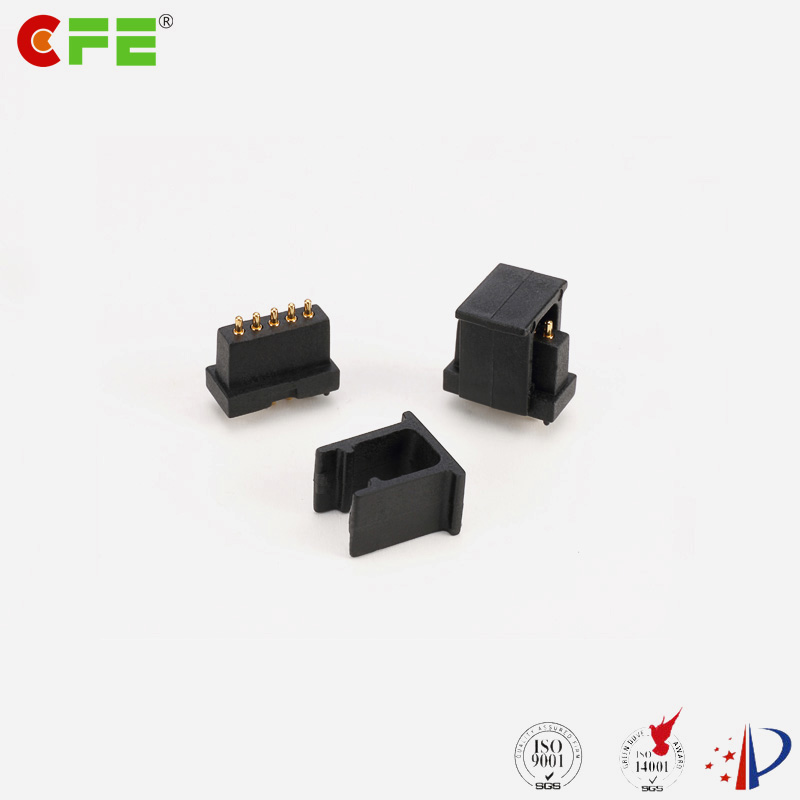
Pin Through Hole

👉🏻👉🏻👉🏻 ALL INFORMATION CLICK HERE 👈🏻👈🏻👈🏻
https://www.panasonicfa.com/content/through-hole
Перевести · Panasonic's pin through hole equipment has a continually-developed, common platform for high …
https://resources.pcb.cadence.com/blog/2019-through-hole-soldering-process-a-guide-for...
Перевести · 11.09.2019 · But that’s not the end of horror stories with through hole soldering. The ground pin is notorious for cracking or drying a …
TIP: #083 Be aware of different connect styles used to connect through hole pins or VIAs
How to solder through-hole (PTH) parts
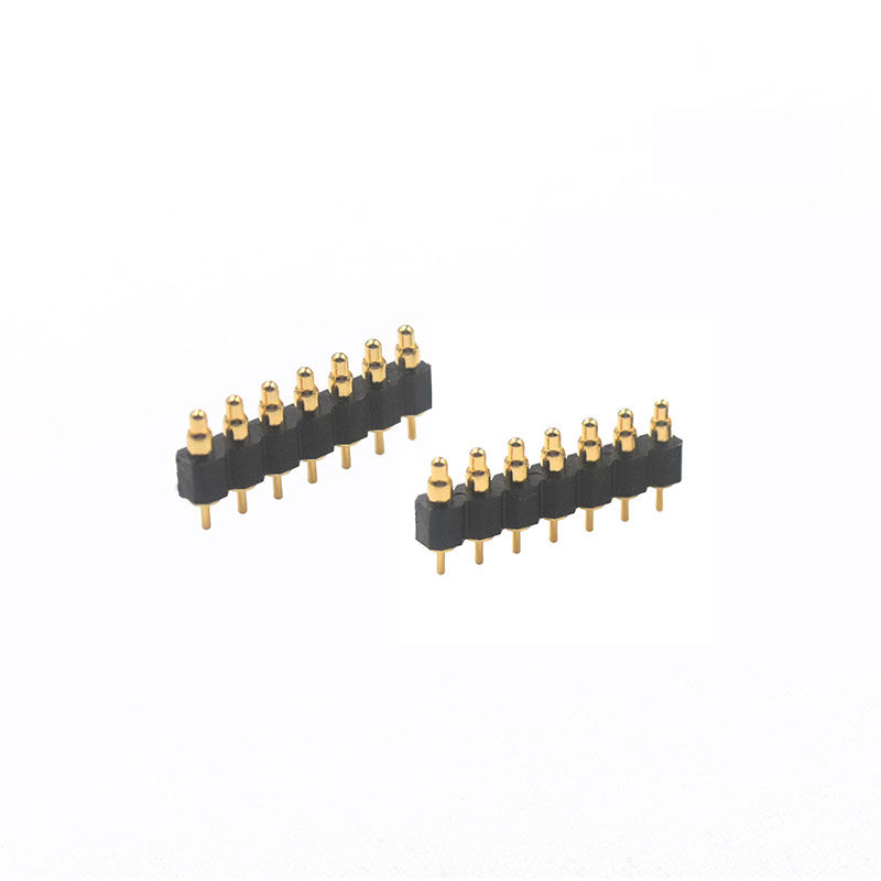
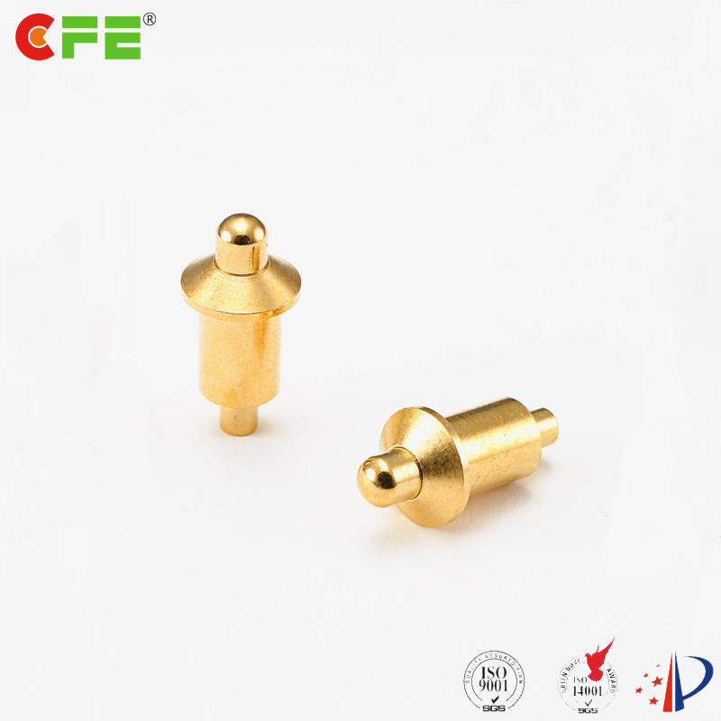
How to solder through hole pogo pins
Desoldering Through Hole Header Pins
OrCAD PCB Design Tutorial - 12 - Create a Through-hole Padstack (2 of 2)
https://en.m.wikipedia.org/wiki/Through-hole_technology
Ориентировочное время чтения: 7 мин
Through-hole technology (also spelled "thru-hole"), refers to the mounting scheme used for electronic components that involves the use of leads on the components that are inserted into holes drilled in printed circuit boards (PCB) and soldered to pads on the opposite side either by manual assembly (hand placement) or by the use of automated insertion mount machines.
m.acronymsandslang.com/definition/954265/PTH-meaning.html
Перевести · What does Technology, IT etc. PTH stand for? Hop on to get the meaning of PTH. The Technology, IT etc. Acronym /Abbreviation/Slang PTH means Pin Through Hole…
https://www.speedingedge.com/PDF-Files/anatomy of a plated hole.pdf
Capture pad- the pads placed on outer layers to “capture” the plated through hole or on inner layers to connect traces to the plated through hole. Capture pads are used on inner layers only when a connection is being made to a trace. Putting capture pads on inner layers where no connections are being mad are called nonfunctional pads and are not beneficial. Note: For mechanical mounting holes …
What happens when you put a pin through a hole?
What happens when you put a pin through a hole?
On the other end of extremes, having too large of a hole makes a component loose when slotting it through. Such situations happen when the component you’re working with are generic parts where there is no guidance on the recommended footprint dimension. You may also encounter issues when soldering the pin onto the pad.
resources.pcb.cadence.com/blog/2019-thro…
How are capture pads used in plated through holes?
How are capture pads used in plated through holes?
Capture pad- the pads placed on outer layers to “capture” the plated through hole or on inner layers to connect traces to the plated through hole. Capture pads are used on inner layers only when a connection is being made to a trace.
www.speedingedge.com/PDF-Files/anatomy…
Can a plated hole pass through an unplated hole?
Can a plated hole pass through an unplated hole?
Note: For mechanical mounting holes that are not plated, there is no need to place capture pads on the outer layers. Clearance hole- the hole etched in a copper plane to allow a drilled hole to pass through. The hole may be plated or unplated. Hole shadow- the shadow cast through all PCB layers by the drilled hole.
www.speedingedge.com/PDF-Files/anatomy…
What happens if you put ground pin on through hole solder?
What happens if you put ground pin on through hole solder?
If the annular ring is too narrow, you’ll find that the solder has difficulties holding onto the pad. And excessive heating may tear off the pad from the PCB base. But that’s not the end of horror stories with through hole soldering. The ground pin is notorious for cracking or drying a solder joint.
resources.pcb.cadence.com/blog/2019-thro…
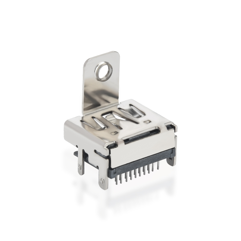
https://gct.co/board-to-board-connector/through-hole-connectors
Перевести · Through hole. Number of Rows Dual. Elevated No. Orientation Straight. Square Pin Size 0.40mm. Profile 1.00mm, 1.50mm, 1.70mm, 2.00mm, 2.50mm, 3.00mm. Insulator Colour Black. Locating …
suddendocs.samtec.com/processing/through-hole-printing.pdf
Paste in Hole, Through Hole printing or Intrusive reflow – printing is quickly becoming a cleaner, more effective alternative to wave soldering as a method for connecting through hole components. This note is a quick reference of the many papers written on this subject and outlines the necessary design criteria for successful printing.
https://www.linguee.com/english-italian/translation/pin+through+hole.html
Перевести · Many translated example sentences containing "pin through hole" – Italian-English dictionary and search engine for Italian translations.
https://de.m.wikipedia.org/wiki/Through_Hole_Technology
Ориентировочное время чтения: 4 мин
Als Durchsteckmontage oder auch Einsteckmontage (englisch through-hole technology, THT; pin-in-hole technology, PIH) bezeichnet man in der Aufbau- und Verbindungstechnik eine Montageweise von bedrahteten elektronischen Bauelementen. Im Gegensatz zur Oberflächenmontage (engl. surface-mounting technology, SMT) ist die Durchsteckmontage dadurch gekennzeichnet, dass die Bauelemente Drahtanschlüsse haben („bedrahtete Bauelemente“). Diese werden bei der Montage durch Kontaktlöcher in der Leiterplattege…
Als Durchsteckmontage oder auch Einsteckmontage (englisch through-hole technology, THT; pin-in-hole technology, PIH) bezeichnet man in der Aufbau- und Verbindungstechnik eine Montageweise von bedrahteten elektronischen Bauelementen. Im Gegensatz zur Oberflächenmontage (engl. surface-mounting technology, SMT) ist die Durchsteckmontage dadurch gekennzeichnet, dass die Bauelemente Drahtanschlüsse haben („bedrahtete Bauelemente“). Diese werden bei der Montage durch Kontaktlöcher in der Leiterplatte gesteckt und anschließend durch Löten (konventionelles Handlöten, Wellenlöten oder Selektivlöten) mit der Leiterbahn verbunden.
Не удается получить доступ к вашему текущему расположению. Для получения лучших результатов предоставьте Bing доступ к данным о расположении или введите расположение.
Не удается получить доступ к расположению вашего устройства. Для получения лучших результатов введите расположение.
For a hole passing completely through an object, see Through hole.
Through-hole technology (also spelled "thru-hole"), refers to the mounting scheme used for electronic components that involves the use of leads on the components that are inserted into holes drilled in printed circuit boards (PCB) and soldered to pads on the opposite side either by manual assembly (hand placement) or by the use of automated insertion mount machines.[1][2]
Through-hole technology almost completely replaced earlier electronics assembly techniques such as point-to-point construction. From the second generation of computers in the 1950s until surface-mount technology (SMT) became popular in the late 1980s, every component on a typical PCB was a through-hole component. PCBs initially had tracks printed on one side only, later both sides, then multi-layer boards were in use. Through holes became plated-through holes (PTH) in order for the components to make contact with the required conductive layers. Plated-through holes are no longer required with SMT boards for making the component connections, but are still used for making interconnections between the layers and in this role are more usually called vias.[2]
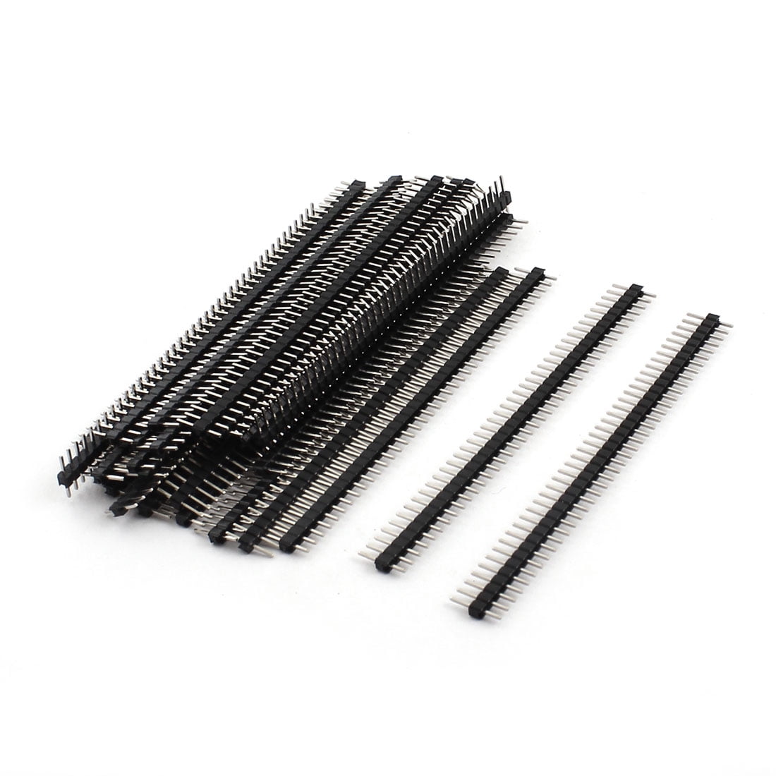
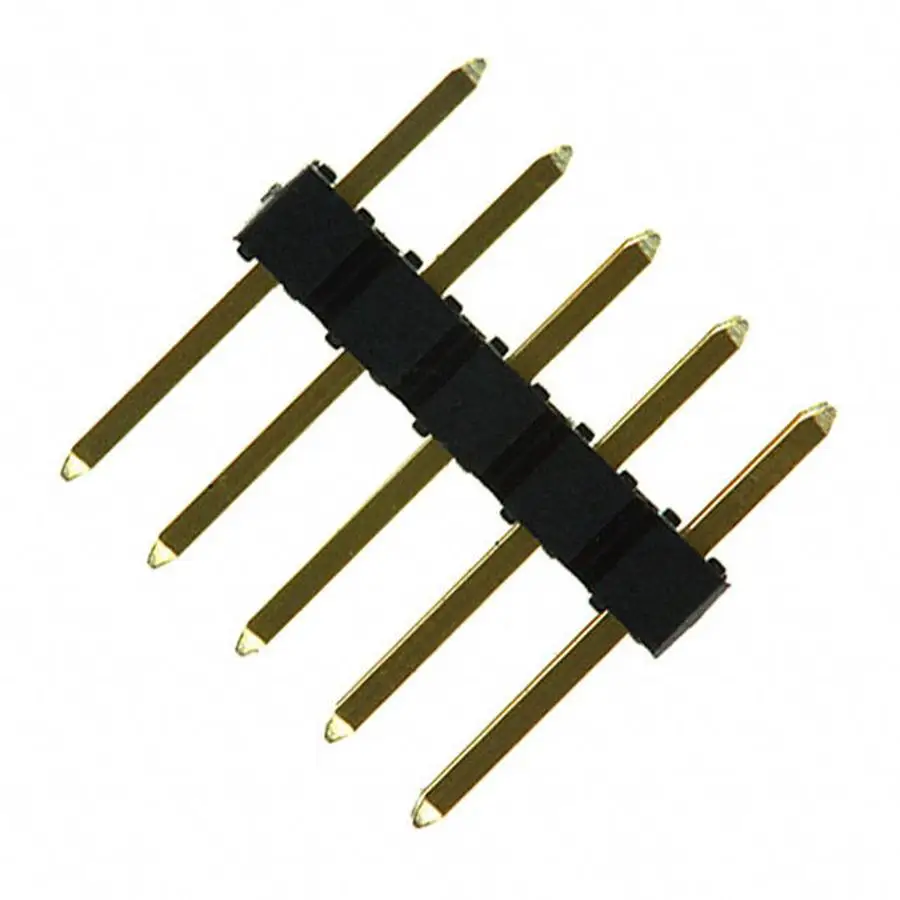
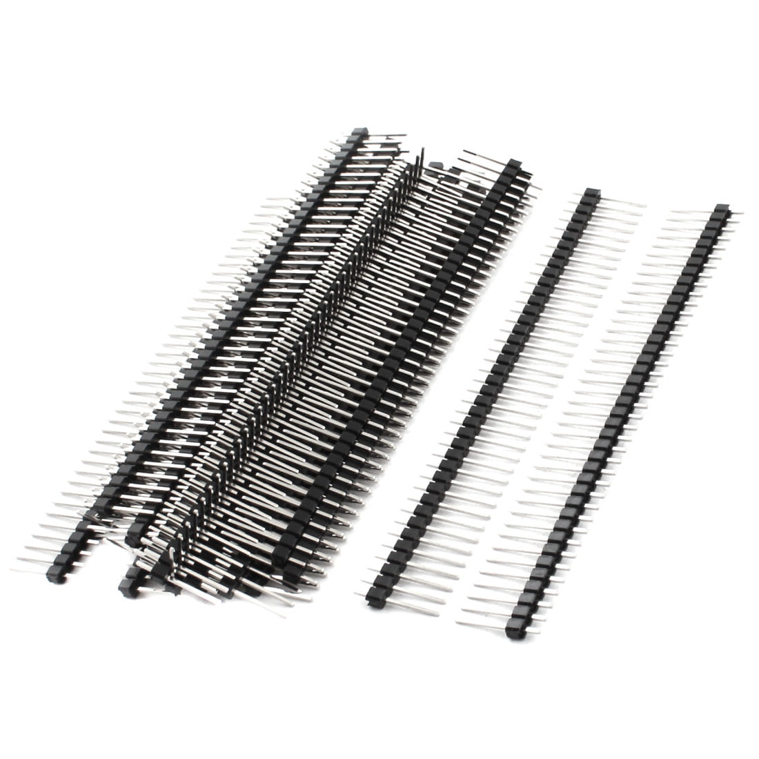
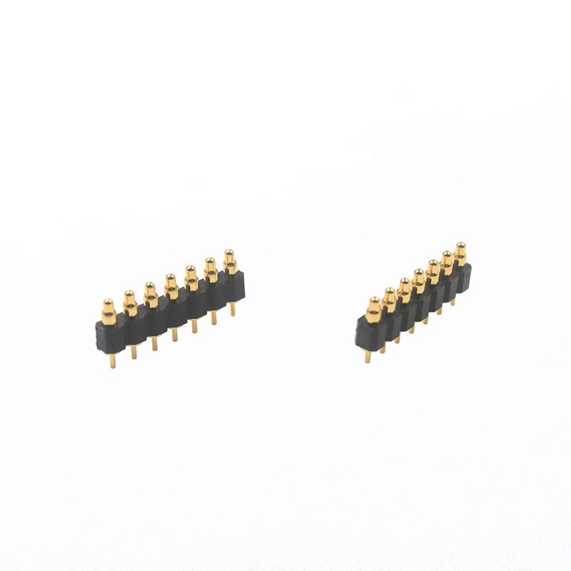
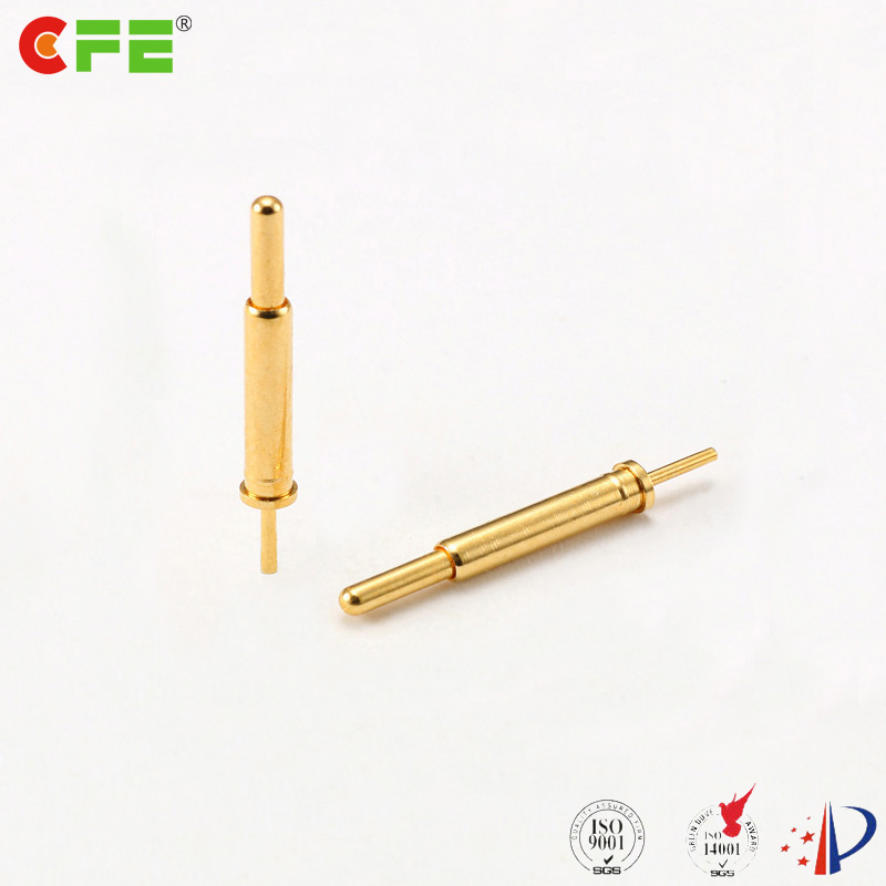
Components with wire leads are generally used on through-hole boards. Axial leads protrude from each end of a typically cylindrical or elongated box-shaped component, on the geometrical axis of symmetry. Axial-leaded components resemble wire jumpers in shape, and can be used to span short distances on a board, or even otherwise unsupported through an open space in point-to-point wiring. Axial components do not protrude much above the surface of a board, producing a low-profile or flat configuration when placed "lying down" or parallel to the board.[3][4][5]
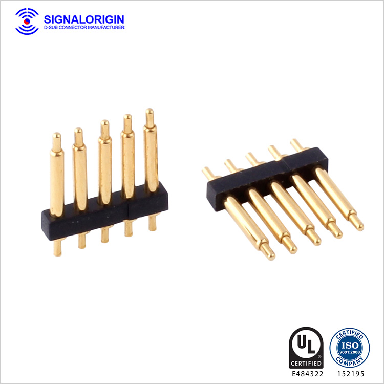
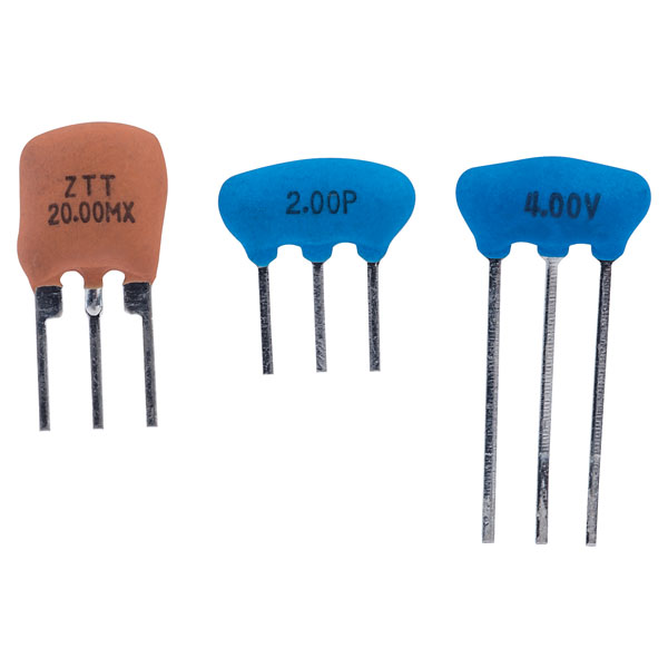
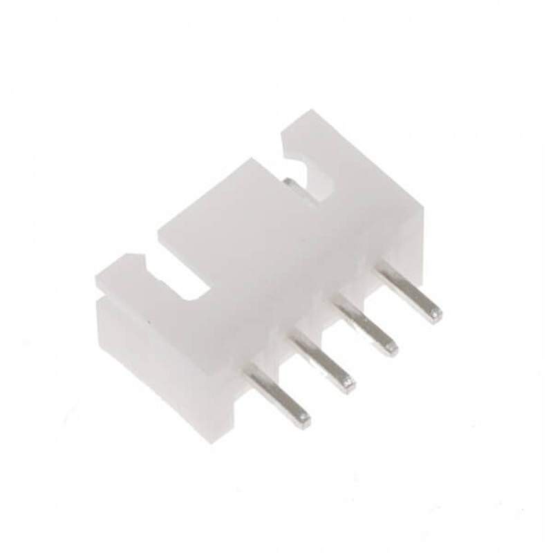
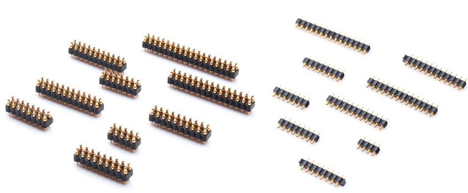
Radial leads project more or less in parallel from the same surface or aspect of a component package, rather than from opposite ends of the package. Originally, radial leads were defined as more-or-less following a radius of a cylindrical component (such as a ceramic disk capacitor).[5] Over time, this definition was generalized in contrast to axial leads, and took on its current form. When placed on a board, radial components "stand up" perpendicular,[3][4] occupying a smaller footprint on sometimes-scarce "board real estate", making them useful in many high-density designs. The parallel leads projecting from a single mounting surface gives radial components an overall "plugin nature", facilitating their use in high-speed automated component insertion ("board-stuffing") machines.
When needed, an axial component can be effectively converted into a radial component, by bending one of its leads into a "U" shape so that it ends up close to and parallel with the other lead.[4] Extra insulation with heat-shrink tubing may be used to prevent shorting out on nearby components. Conversely, a radial component can be pressed into service as an axial component by separating its leads as far as possible, and extending them into an overall length-spanning shape. These improvisations are often seen in breadboard or prototype construction, but are deprecated for mass production designs. This is because of difficulties in use with automated component placement machinery, and poorer reliability because of reduced vibration and mechanical shock resistance in the completed assembly.
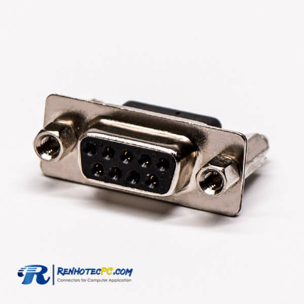
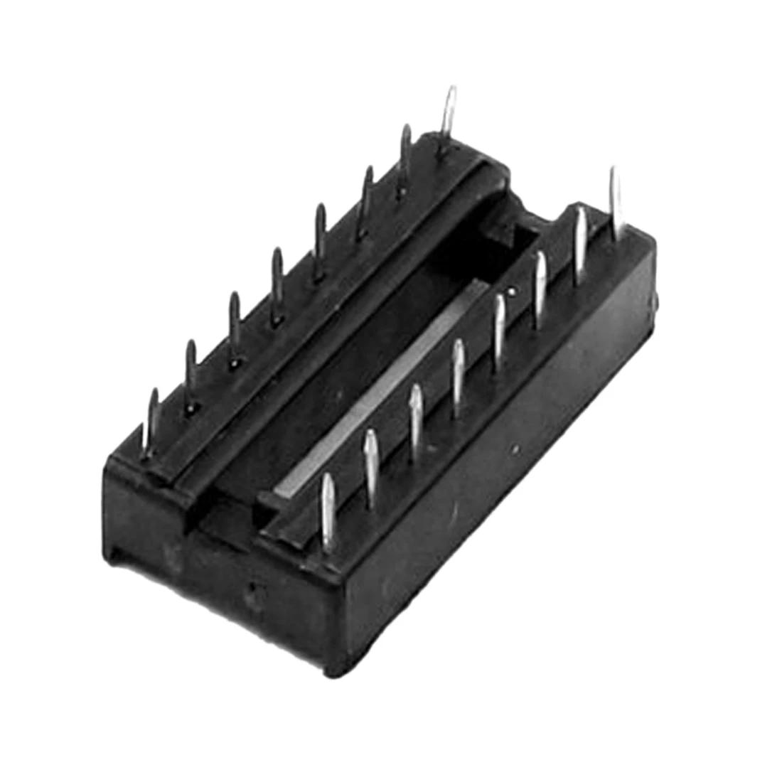
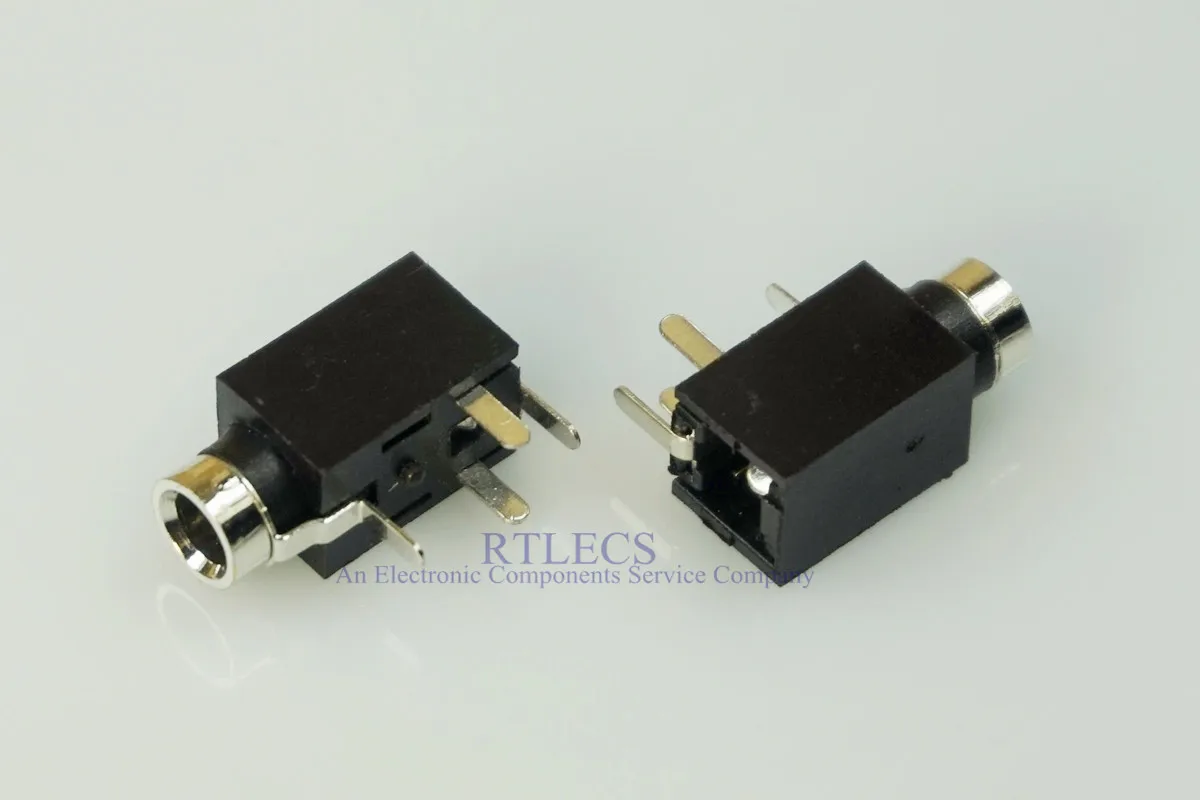
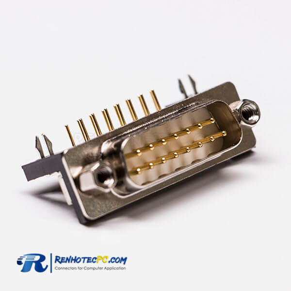
For electronic components with two or more leads, for example, diodes, transistors, ICs, or resistor packs, a range of standard-sized semiconductor packages are used, either directly onto the PCB or via a socket.
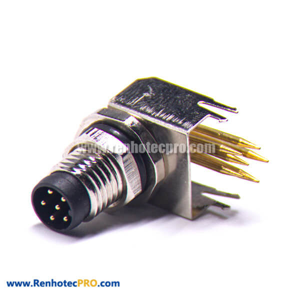
While through-hole mounting provides strong mechanical bonds when compared to SMT techniques, the additional drilling required makes the boards more expensive to produce. They also limit the available routing area for signal traces on layers immediately below the top layer on multilayer boards since the holes must pass through all layers to the opposite side. To that end, through-hole mounting techniques are now usually reserved for bulkier or heavier components such as electrolytic capacitors or semiconductors in larger packages such as the TO-220 that require the additional mounting strength, or for components such as plug connectors or electromechanical relays that require great strength in support.[4]
Design engineers often prefer the larger through-hole rather than surface mount parts when prototyping, because they can be easily used with breadboard sockets. However, high-speed or high-frequency designs may require SMT technology to minimize stray inductance and capacitance in wire leads, which would impair circuit function. Ultra-compact designs may also dictate SMT construction, even in the prototype phase of design.
Through-hole components are ideal for prototyping circuits with breadboards using microprocessors such as Arduino or PICAXE. These components are large enough to be easy to use and solder by hand.
^ Electronic Packaging:Solder Mounting Technologies in K.H. Buschow et al (ed), Encyclopedia of Materials:Science and Technology, Elsevier, 2001 ISBN 0-08-043152-6, pages 2708-2709
^ a b Horowitz, Paul; Hill, Winfield (1989). The art of electronics (PDF) (2nd ed.). Cambridge [u.a.]: Cambridge Univ. Press. ISBN 9780521370950.
^ a b "All About Capacitors". Beavis Audio Research. Retrieved 2013-05-16.
^ a b c d "What Is an Axial Lead?". wiseGEEK: clear answers for common. Conjecture Corporation. Retrieved 2013-05-16.
^ a b Bilotta, Anthony J. (1985). Connections in electronic assemblies. New York: M. Dekker. p. 205. ISBN 9780824773199.
Content is available under CC BY-SA 3.0 unless otherwise noted.
Best Female Dating Headlines
Teen School Model Naked
Old Mom And Boy Porn
Japanese Wife Porno Hd
Www Xxx 15
Panasonic Pin Through Hole Equipment | PTH Solutions
Through Hole Soldering Process: A Guide for PCB Design ...
Through-hole technology - Wikipedia
PTH - Pin Through Hole in Technology, IT etc. by ...
ANATOMY OF A PLATED THROUGH HOLE - Speeding Edge
Thru Hole Board to Board Connectors | Products | GCT
Through Hole Printing - Samtec
pin through hole - Italian translation – Linguee
Durchsteckmontage – Wikipedia
Pin Through Hole