Metal Foil Resistors
Charly GarcíaJuly 15, 2022Index
4) Heat treatment
Manipulation of the TCR in metals. 1 ,document explaining the adjustment of the TCR to compensate for variations in resistance due to thermal effects is performed by heat treatment of the metal foil.
Manipulation of the TCR in metals.2 , in the first part of the heat treatment process of the metal foil, it was described, based on work carried out over time by academic and industrial researchers. In this second part, the processes and equipment used are described in more detail.
Index of YouTube pages.
Thermal treatment TCR 1 , this document is a video with a brief explanation of the concept of the Temperature Coefficient of Resistance, TCR and its adjustment by means of a thermal treatment as well as the description of the Evanohm S alloy from which the metal foil is made where it will be created. the resistance.
Preface.
Preface: The following document is a study of the metal foil resistors, which is based on the original works were published in books and on the Internet, the reader is referred to the links from each of the themes are based only in these documents, and certain paragraphs are originals of different researchers, I have added some comments to coordinate them. This paper, which is a record, makes no attempt to provide a comprehensive scholarly treatment of the metal foil resistors. Such a work apparently does not exist at this time, however, acknowledgment must be given to several valuable papers and bibliographies contributed by specialists in this field that, collectively tell much of the story of this important technology development from an engineering perspective. This paper is intended to build on these past works, focusing on the associated engineering issues. Given the finite length of this paper, attention has been focused on a limited number of technological highlights in the development of metal foil resistors. The author regret any unintentional historical oversights or inaccuracies that appear in this manuscript.
Foil resistors have been the leading in precision and stability. One of the important parameters influencing stability, is the Temperature Coefficient of Resistance (TCR).
The resistance change versus temperature is a non-linear function, and it is extremely low to begin with. Therefore the key to improve further the temperature dependency was to find a way to linearize this function, or to reduce the non linear component first, and then reduce the slope (linear component) of resistance versus temperature(TCR) to zero or as close to zero as possible.[3]
The building block used for Bulk Metal Foil (BMF) products is the chip resistor element. The chip consists of a homogeneous metal foil bonded by an adhesive layer on a ceramic substrate.
The following drawing is a very schematic representation of the components of the metal foil resistor, it is based on a study by Hero Faierstein [5] and regarding the metal used the Evanohm is based on a study by Mark Robinson, the study is called Strain Gage Materials Processing, Metallurgy and Manufacture [1] Mark Robinson Hamilton Precision Metals1780 Rohrerstown Road Lancaster, PA 17601
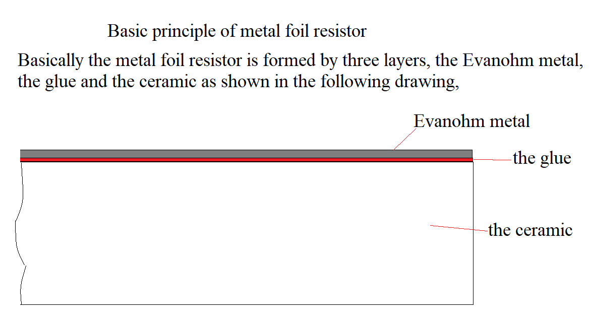
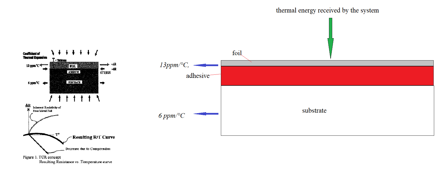
The unique combination of materials and construction provides superior performances that are unavailable all in one resistor in other technologies. The extremely low TCR is one of the main features of the foil technology. Two opposing physical phenomena within the chip are the key of the low TCR capability of BMF:
Resistance of the foil in its free state (before bonding to a substrate) increases when temperature rises since foil is cemented to the much thicker ceramic substrate and since the coefficient of thermal expansion of ceramic is smaller than the thermal coefficient of expansion of the foil (typically 6 ppm/°C versus13ppm/°C, respectively), as the temperature increases the foil undergoes compressive stress. Resistance of the foil decreases due to compression The result of matching these two simultaneous effects is a low and predictable TCR .
Operations to be carried out to manufacture the metallic film resistance.
In the book ,"Resistor Theory and Technology", whose authors are, Felix Zandman, Paul Rene Simon and Joseph Szwarc, from 2001, on pages 156 and 158 , it is described the basic steps of this process , each part of the description is expanded by the work of other researchers .[6]
"These resistors based on strain gage technology for manufacturing state-of-art precision resistors"
"These resistors based on strain gage technology are made as follows, A foil of resistive Ni-Cr, or similar alloy, with a thickness of 2-8 µm is glued to a solid ceramic or glass substrate after being heat treated to adjust its temperature coefficient of resistance (TCR) to an appropriate value. A phosensitive resin is then deposited on the foil using micro-electronic processes, similar to integrate circuit process technology. The photosensitive resin is exposed (photolithography) through a photographic mask representing the design of resistance circuit, which resembles a series of looping filaments. The nonexposed areas are washed off, leaving the exposed areas intact, forming a meander pattern (phoresist mask) on top of the foil. The foil areas not protected by the photoresist mask are then etched by means of electrolytic or chemical processes, reproducing the design of the mask. This step creates hundreds of resistive filaments in series or parallel such that the resistance of the circuit reaches the desired value. Such resistance elements are usually produced in an array of several hundred on a wafer. The next process step is to singulate resistor chips from the wafer.” “To complete the resistor, leads are soldered or welded to each end of the resistive circuit on the chip. The foil resistors are then usually calibrated in discrete increments”
Bulk Metal Foil technology outperforms all other resistance technologies available today for applications that require precision and stability. Bulk metal foil products are offered in a variety of configurations and package types to meet the needs of a wide range of applications. Manufactured bulk metal foil products offer an absolute temperature coefficient of resistance (TCR) of ±0.2 ppm/°C (–55°C to +125°C, +25°C ref), an order magnitude better than previous foil technologies. [3]
The lower the absolute TCR, the better a resistor can maintain its precise value despite ambient temperature variations and self-heating when power is applied.
The following drawing shows in a very simplified way the manufacturing process of the metal foil resistor.[2]
The manufacturer of this component must acquire the alloy called Evanohm, from one of the companies that supplies said alloy, which may be Hamilton Precision Metals. [1]
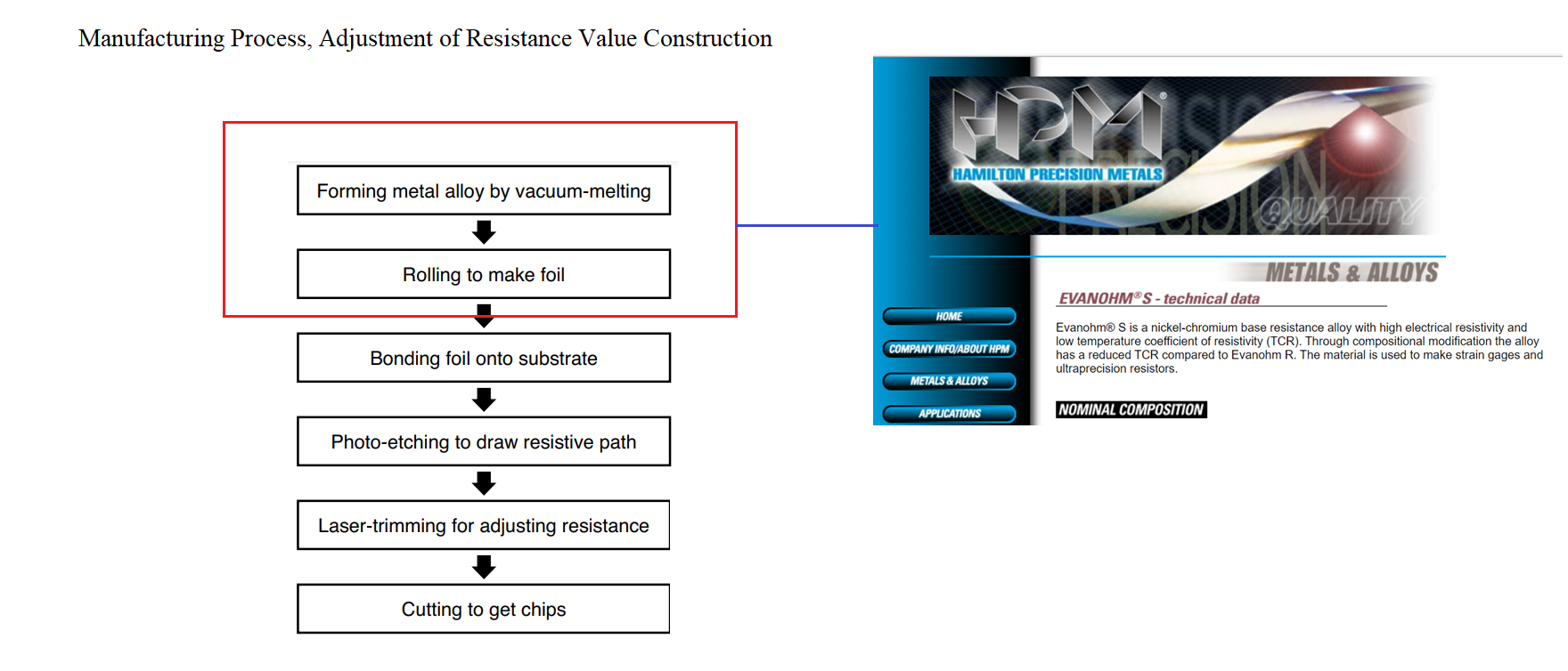
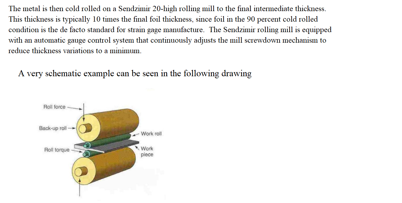
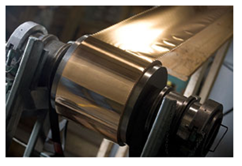
When obtaining an alloy with a thickness between 2-8 [µm], it is rolled as indicated below. [7].
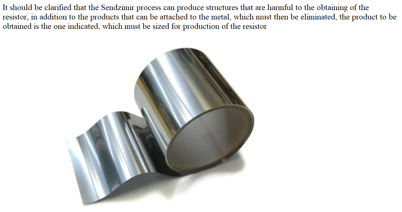
Then the metal foil is cut to the measurements used in the production of the component, in these conditions the metal foil must be cleaned of impurities adhered to its surface such as the oil from the machines used in the previous steps, among others.
For this, a succession of baths, some electrolytes and the use of distilled hot water with very low conductivity are used. [8].
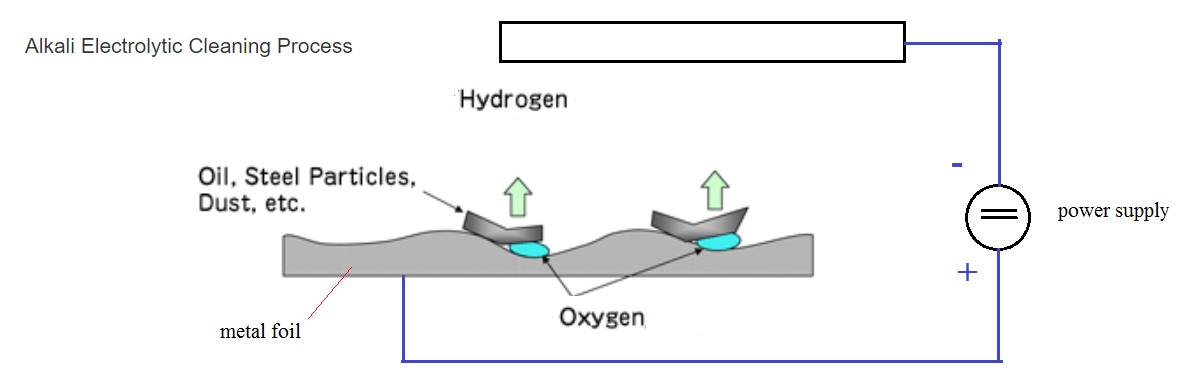
The previous drawing represents the cleaning process, since the metal foil is the anode, the released oxygen pushes the impurities out of it.
Next, the metal foil must be subjected to a thermal treatment to bring its characteristics to a production level and especially its temperature coefficient of resistance, TCR, [6], see Manipulation of the TCR in metals. 1
Then from the component design, [9]. perform the operations indicated in the following illustration.
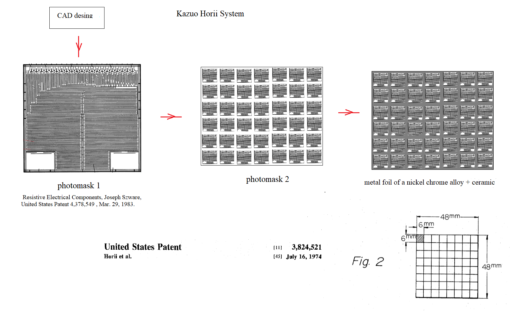
A resistive pattern is then photographed on the metal foil. This process combines the important features of low TCR, long-term stability, non-inductance, electrostatic discharge, ESD insensitivity, low capacitance, fast thermal stabilization, and low noise in a single resistor technology. To acquire a precision resistance value, the Bulk Metal Foil chip is trimmed by selectively removing the built-in "shorting bars".[2]
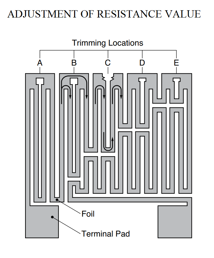
To increase resistance in known increments, selected areas are cut, resulting in progressively smaller resistance increases.
In the flat sheet, the parallel pattern element design reduces inductance, the maximum total inductance of the resistor is 0.08 μH. The capacitance is 0.5 pF maximum. A 1 kΩ resistor has a rise time of less than 1 ns up to 100 MHz. The rise time depends on the value of the resistor, but the higher and lower values are only slightly slower than the mid-range values. The absence of ringing is especially important in high-speed switching, such as signal conversion. The DC resistance of a 1 kΩ bulk metal foil resistor compared to its AC resistance at 100 MHz can be expressed as: AC resistance / DC resistance = 1.001. Foil techniques produce a combination of highly desirable and previously unattainable strength specifications. By taking advantage of the overall stability and reliability of VFR resistors, designers can significantly reduce circuit errors and greatly improve overall circuit performance.
Despite all the benefits mentioned above, it is an expensive component that requires extreme care during installation in systems and especially in those where repair is impossible, such as an aerospace system.
Historical summary of the development of Metal Foil Resistors.
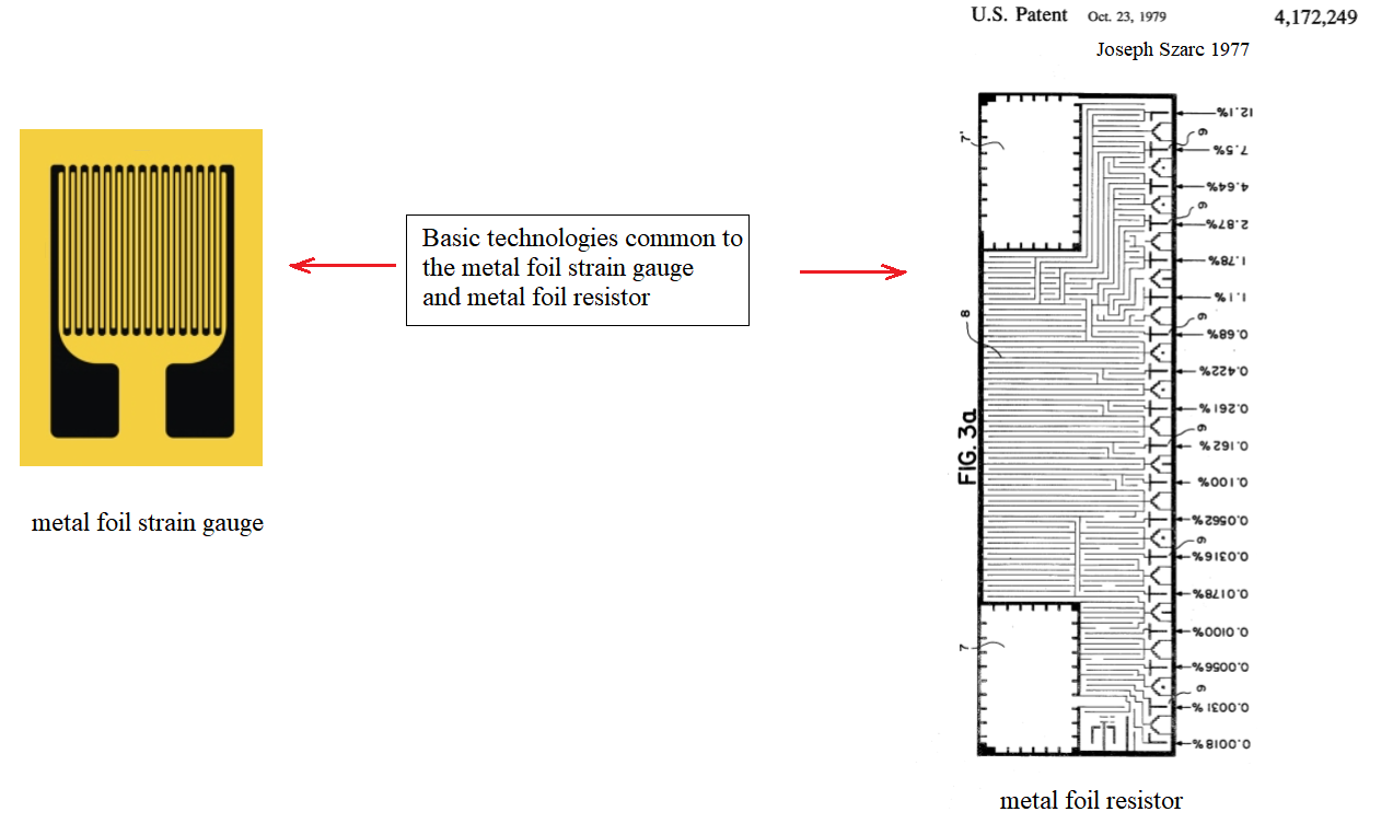
The technologies used for the manufacture of metal foil strain gauge and metal foil resistors have elements common to both and this is illustrated below.

The history of the metal foil resistor and the strain gauge are linked, due to the similarity of their construction and their problems, the operation of the metal foil resistor is highly influenced by the forces that act on the system, drastically modifying its response and with this cannot make the element respond as desired. As it is a metal foil bonded to a ceramic, it behaves like a strain gauge and all physical analysis must be carried out with strain gauge engineering.The similarity between the strain gauge and the metal foil resistor is reflected in the following illustration, on the left side you can see a strain gauge manufactured in 1963 by the company Denyssen in the USA and on the right side a metal foil resistor manufactured by the Institute of Electrical Engineers of Japan, in 2011, following the same procedures. [10]
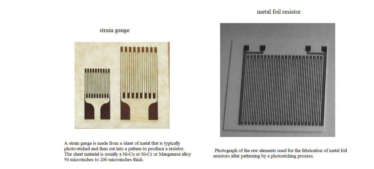
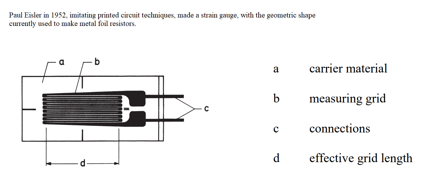
Paul Eisler in 1952, imitating printed circuit techniques, made a strain gauge, with the geometric shape currently used to make metal foil resistors.
Bibliography.
[1] Strain Gage Materials, Processing, Metallurgy and Manufacture, Mark Robinson
Hamilton Precision Metals, 1780 Rohrerstown Road
Lancaster, PA 17601
[2] Manufacturing Process, Adjustment of Resistance Value Construction, and Temperature Characteristics of Resistance. Alpha Electronics. (7)
[3] Zero TCR Foil Resistor Ten Fold Improvement in Temperature Coefficient Reuven Goldstein and Joseph Szwarc .
[5] Hero Faierstein. NEW HIGH - PRECISION FOIL RESISTORS FOR SPACE PROJECTS, WITH ZERO TEMPERATURE COEFFICIENT, VERY LOW POWER COEFFICIENT AND HIGH RELIABILITY .
[6] "Resistor Theory and Technology", whose authors are, Felix Zandman, Paul Rene Simon and Joseph Szwarc.
[7] Hamilton Precision Metals.
[8] Alkaline Cleaning Guide, Products Finishing.
[9] Resistive Electrical Components, Joseph Szware, United States Patent 4,378,549 , Mar. 29, 1983.
[10] Novel 100-Ω Metal Foil Resistor Yasuhiko Sakamoto, Member, IEEE, Nobu-hisa Kaneko, Takehiko Oe, Associate Member, IEEE, Masaya Kumagai, and Matsuo Zama.