Lora Spread

🛑 ALL INFORMATION CLICK HERE 👈🏻👈🏻👈🏻
Lora Spread
Login or Register
SUPPORT
EVENTS
NEWS
SEMTECH.COM
HOME » LIBRARY » TECHNICAL DOCUMENTS » LoRa® and LoRaWAN®
Download
« RETURN TO TECH PAPERS AND GUIDES
Resources
Library
Knowledge Base
Tech Journal
Support
Events
News
Security
Subscribe:
Sign Up for the LoRa Developer Portal Newsletter
SUBSCRIBE
Follow Us:
YOUTUBE
PRIVACY POLICY
Terms & Conditions
© All rights reserved
Effective July 1, 2020, we've updated our Privacy Policy with additional details about the data we collect and how we use it. We do not sell any personal information. Our updated policy also explains our compliance with the California Consumer Privacy Act. The full policy can be read at https://www.semtech.com/legal .
This site uses cookies. By continuing to use our website, you consent to our Privacy Policy . If you access other websites using the links provided, please be aware they may have their own privacy policies, and we do not accept any responsibility or liability for these policies or for any personal data which may be collected through these sites. Please check these policies before you submit any personal information to these sites.
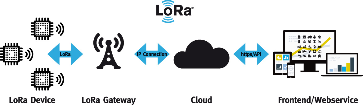
LoRa is an RF modulation technology for low-power, wide area networks (LPWANs). The name, LoRa, is a reference to the extremely lo ng- ra nge data links that this technology enables. Created by Semtech to standardize LPWANs, LoRa provides for long-range communications: up to three miles (five kilometers) in urban areas, and up to 10 miles (15 kilometers) or more in rural areas (line of sight). A key characteristic of the LoRa-based solutions is ultra-low power requirements, which allows for the creation of battery-operated devices that can last for up to 10 years. Deployed in a star topology, a network based on the open LoRaWAN protocol is perfect for applications that require long-range or deep in-building communication among a large number of devices that have low power requirements and that collect small amounts of data.
Consider the differences between LoRa and other network technologies that are typically used in IoT or traditional machine-to-machine (M2M) connectivity solutions:
Note: In Europe, mobile network operators have implemented a dual strategy to address packet size and latency issues. They often offer both LoRaWAN and Cat-M1, which are complementary technologies. LoRaWAN accommodates the need for longer battery life, with a trade-off of longer latency and smaller packet sizes. In contrast Cat-M1 can be used for larger payloads with less latency than LoRaWAN can accommodate.
Figure 2 highlights some important advantages of deploying a LoRaWAN network:
Figure 2: Advantages of deploying a LoRaWAN network
Let’s look into these advantages in a little more depth.
With respect to range, a single LoRa-based gateway can receive and transmit signals over a distance of more than 10 miles (15 kilometers) in rural areas. Even in dense urban environments, messages are able to travel up to three miles (five kilometers), depending on how deep indoors the end devices (end nodes) are located.
As far as battery life goes, the energy required to transmit a data packet is quite minimal given that the data packets are very small and only transmitted a few times a day. Furthermore, when the end devices are asleep, the power consumption is measured in milliwatts (mW), allowing a device’s battery to last for many, many years.
When it comes to capacity, a LoRaWAN network can support millions of messages. However, the number of messages supported in any given deployment depends upon the number of gateways that are installed. A single eight-channel gateway can support a few hundred thousand messages over the course of a 24-hour period. If each end device sends 10 messages a day, such a gateway can support about 10,000 devices 1 . If the network includes 10 such gateways, the network can support roughly 100,000 devices and one million messages. If more capacity is required, all that is needed is to add additional gateways to the network.
And then, there is cost. Given the capabilities of LoRa-based end nodes and gateways, only a few gateways – configured in a star network – are required to serve a multitude of end nodes. This means that capital and operational expenses can be kept relatively low. Also, when the cost-effective LoRa RF modules that are embedded in inexpensive end nodes are used in conjunction with the open LoRaWAN standard, the return on investment can be considerable.
A proprietary spread-spectrum modulation technique derived from existing Chirp Spread Spectrum (CSS) technology, LoRa offers a trade-off between sensitivity and data rate, while operating in a fixed-bandwidth channel of either 125 KHz or 500 KHz (for uplink channels), and 500 KHz (for downlink channels). Additionally, LoRa uses orthogonal spreading factors. This allows the network to preserve the battery life of connected end nodes by making adaptive optimizations of an individual end node’s power levels and data rates. For example, an end device located close to a gateway should transmit data at a low spreading factor, since very little link budget is needed. However, an end device located several miles from a gateway will need to transmit with a much higher spreading factor. This higher spreading factor provides increased processing gain, and higher reception sensitivity, although the data rate will, necessarily, be lower.
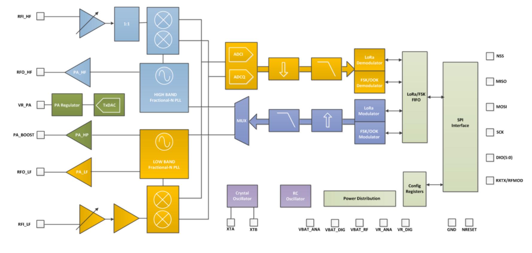
LoRa is purely a physical (PHY), or “bits” layer implementation, as defined by the OSI seven-layer Network Model, depicted in Figure 3. Instead of cabling, the air is used as a medium for transporting LoRa radio waves from an RF transmitter in an IoT device to an RF receiver in a gateway, and vice versa.
1 There is no one-to-one relationship between LoRa-based devices and gateways in a LoRaWAN network; messages sent to and from end devices travel through all gateways within range. Deduplication is handled by the network server.
Figure 3: OSI seven-layer network model
In a traditional or Direct Sequence Spread Spectrum (DSSS) system, the carrier phase of the transmitter signal changes according to a code sequence as shown in Figure 4. When multiplying the data signal with a pre-defined bit pattern at a much higher rate, also known as a spreading code (or chip sequence), a “faster” signal is created that has higher frequency components than the original data signal. This means that the signal bandwidth is spread beyond the bandwidth of the original signal. In RF terminology, the bits of the code sequence are called chips (in order to distinguish between the longer, un-coded, bits of the original data signal). When the transmitted signal arrives at the RF receiver, it is multiplied with an identical copy of the spreading code used in the RF transmitter, resulting in a replica of the original data signal.
Figure 4: DSSS system carrier phase transmitter signal changes
You might ask: Why go through all this trouble? Why not just transmit the original data signal instead of going through this code sequence multiplication? The answer is simple: going through this code sequence multiplication buys you a higher RF link budget, so you can transmit over a longer range.
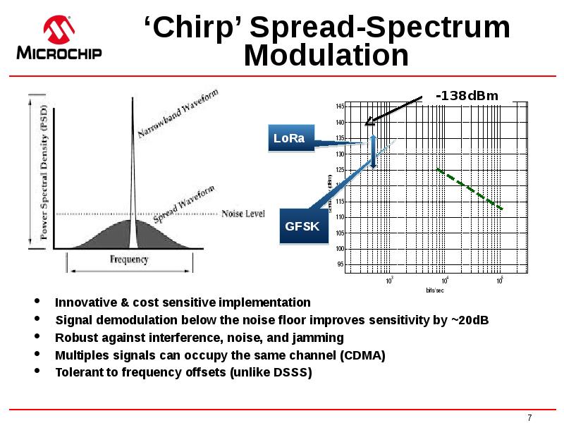
The Log10 ratio of the code sequence’s chip rate and the data signal’s bit rate is called the processing gain (Gp). This gain is what allows the receiver to recover the original data signal, even if the channel has a negative signal-to-noise ratio (SNR). LoRa has a superior Gp compared to frequency-shift keying (FSK) modulation, allowing for a reduced transmitter output power level while maintaining the same signal data rate and a similar link budget.
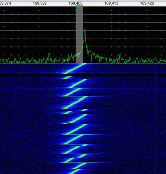
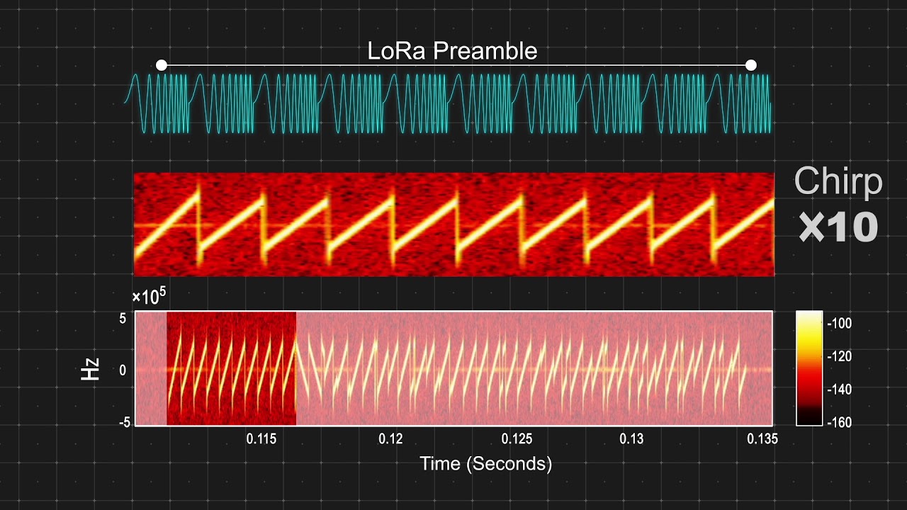
One of the downsides of a DSSS system is the fact that it requires a highly-accurate (and expensive) reference clock. Semtech’s LoRa Chirp Spread Spectrum (CSS) technology offers a low-cost and low-power, yet robust, DSSS alternative that does not require a highly-accurate reference clock. In LoRa modulation, the spreading of the signal’s spectrum is achieved by generating a chirp signal that continuously varies in frequency, as is depicted in Figure 5.
Figure 5: LoRa Chirp Spread Spectrum illustration
An advantage of this method is that the timing and frequency offsets between transmitter and receiver are equivalent, greatly reducing the complexity of the receiver design. The frequency bandwidth of this chirp is equivalent to the spectral bandwidth of the signal. The data signal that carries the data from an end device to a gateway is chipped at a higher data rate and modulated onto the chirp carrier signal. LoRa modulation also includes a variable error correction scheme that improves the robustness of the transmitted signal. For every four bits of information sent, a fifth bit of parity information is sent.
As noted above, LoRa processing gain is introduced in the RF channel by multiplying the data signal with a spreading code or chip sequence. By increasing the chip rate, we increase the frequency components of the total signal spectrum. In other words, the energy of the total signal is now spread over a wider range of frequencies, allowing the receiver to discern a signal with a lower (that is, worse) signal-to-noise ratio (SNR).
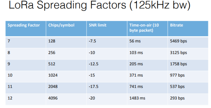
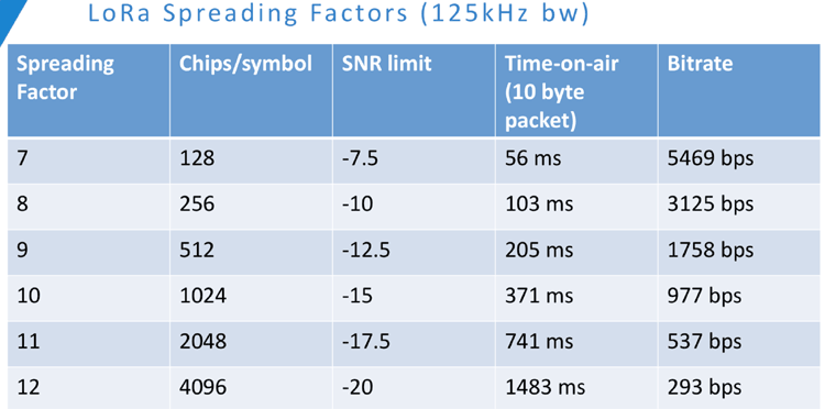
In LoRa terms, the amount of spreading code applied to the original data signal is called the spreading factor (SF). LoRa modulation has a total of six spreading factors (SF7 to SF12). The larger the spreading factor used, the farther the signal will be able to travel and still be received without errors by the RF receiver.
Table 1 shows the four different spreading factors [SF7…SF10] that can be used for uplink (UL) messages on a 125 KHz channel 2 . It shows the equivalent bit rate as well as the estimated range (this depends on the terrain; longer distances will be achieved in a rural environment thank in an urban environment). It also shows the dwell time, or time on air (TOA), values for an 11-byte payload for each of the four spreading factors.
2 Downlink messages broadcast over 500 KHz channels can use all six available spreading factors (SF7…SF12).
Importantly, the LoRa modulation spreading factors are inherently orthogonal. This means that signals modulated with different spreading factors and transmitted on the same frequency channel at the same time do not interfere with each other. Instead, signals at different spreading factors simply appear to be noise to each other.
LoRa signals are robust and very resistant to both in-band and out-of-band interference mechanisms. LoRa modulation also offers immunity to multipath and fading, making it ideal for use in urban and suburban environments, where both mechanisms dominate. Additionally, Doppler shifts cause a small frequency shift in the time axis of the baseband signal. This frequency offset tolerance mitigates the requirement for tight tolerance reference clock sources and, therefore, makes LoRa ideal for data communications from devices that are mobile.
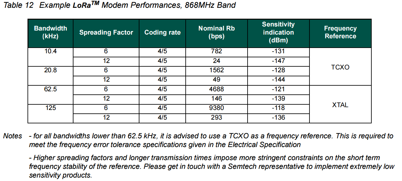
The LoRa modulation characteristics for each region are defined in the LoRaWAN Regional Parameters document, available from the LoRa Alliance® ( https://lora-alliance.org/resource-hub/rp002-100-lorawanr-regional-parameters ). In North America, there are 64, 125 kHz LoRa uplink channels defined, centered on a 200 kHz raster as can be seen in Figure 5. 11. There are eight 500 kHz uplink channels as well as eight, 500 kHz downlink channels defined. In North America, gateways can have up to 64, 125 kHz uplink channels as well as eight 500 kHz uplink and downlink channels. This type of gateway is referred to as a carrier grade macro gateway and is used for outdoor applications only.
Figure 6: LoRa modulation characteristics
Table 2 provides another way to understand these modulation characteristics.
Table 2: LoRa modulation characteristics
As Stephan Hengstler asserts in his book, A Novel Chirp Modulation Spread Spectrum technique for Multiple Access , “LoRa is a constant envelope modulation (very low cost, power efficient power amplifier implementation) … [it] is the most robust, ultra-low power and long range RF solution available.”
With LoRa, packets using different spreading factors are orthogonal, meaning that they are invisible to each other: as mentioned earlier, they simply appear as noise to one another. Therefore, two packets that arrive at the same time on the same receive channel at different spreading factors will not collide and, both will be demodulated by the gateway modem chip. However, two packets with the same spreading factor arriving at the same time on the same channel might result in a collision. However if one of the two packets is stronger by six dB, it will survive.
The capacity of a LoRaWAN network is a function of its gateway density. To maximize the capacity of the network, using an adaptive data rate (ADR) mechanism is essential. The main goal of ADR is to save the battery power of the LoRaWAN end-nodes. By having the end-nodes closest to a gateway transmit using the lowest spreading factor, their time on air is minimized, thereby prolonging their battery life. More distant sensors transmit at a higher spreading factor. A trade-off is made between battery power and distance given that a higher spreading factor allows for a gateway to connect to devices that are farther away.
To fully understand LoRaWAN networks, we will start with a look at the technology stack. As shown in Figure 7, LoRa is the physical (PHY) layer, i.e., the wireless modulation used to create the long-range communication link. LoRaWAN is an open networking protocol that delivers secure bi-directional communication, mobility, and localization services standardized and maintained by the LoRa Alliance.
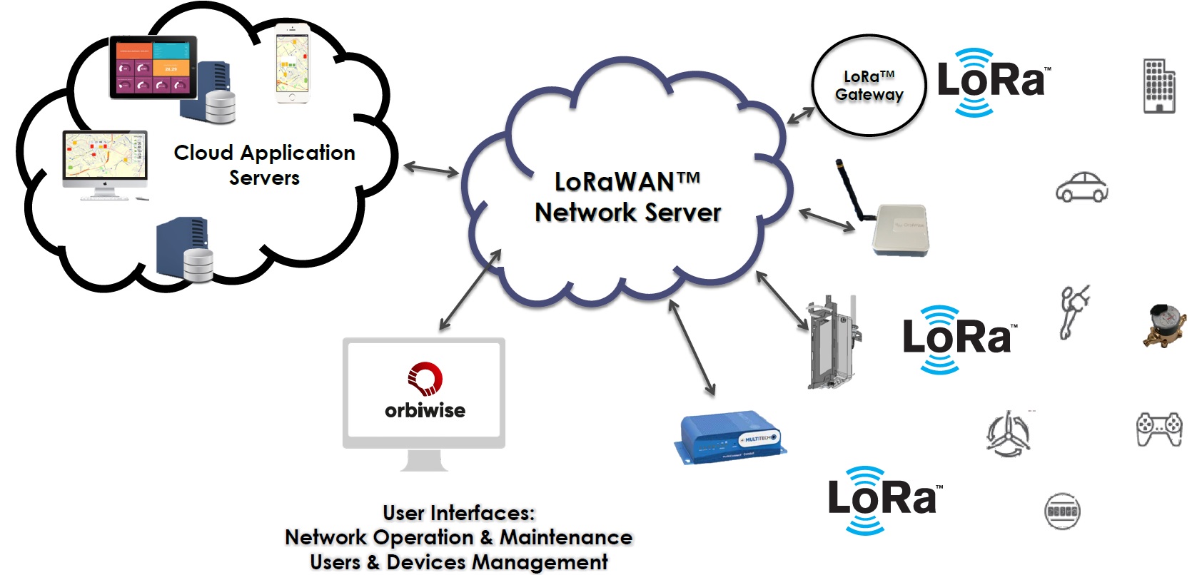
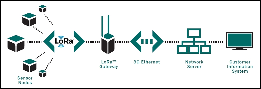
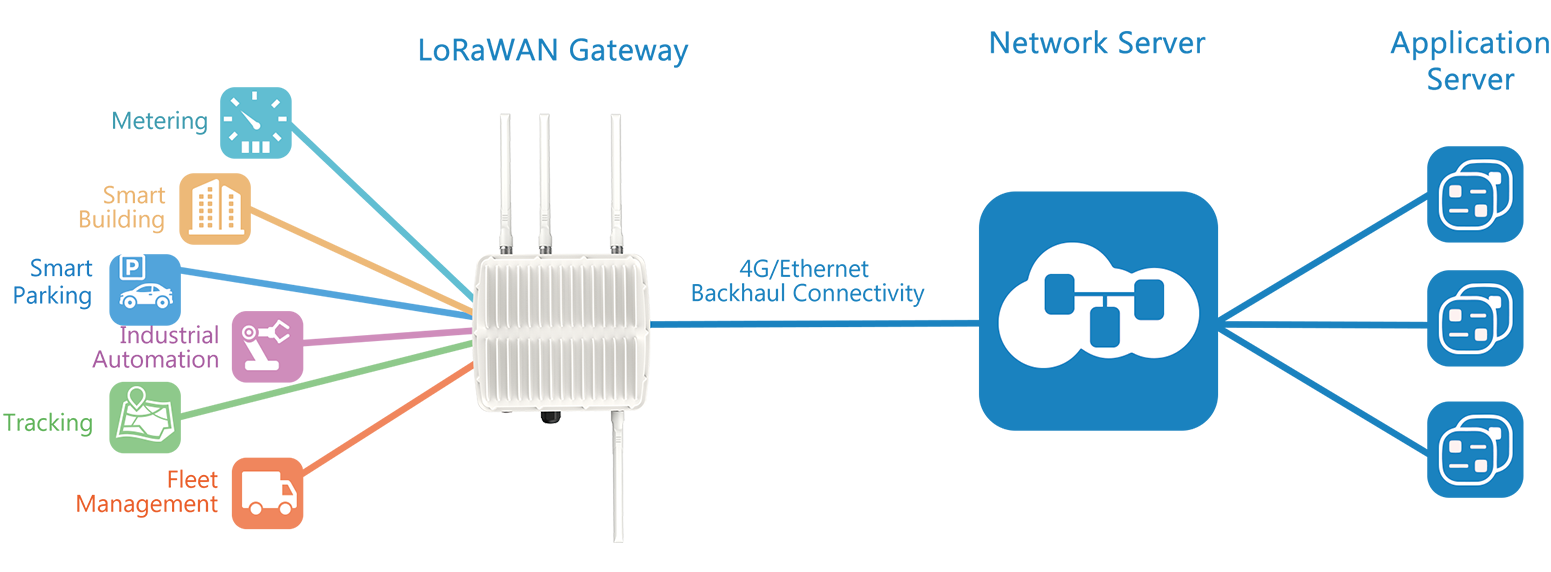
Now that we have a basic understanding of LoRa, we will examine the architecture of a LoRaWAN network. Figure 8 shows a typical LoRaWAN network implementation from end to end.
Figure 8: Typial LoRaWAN network implementation
Let us examine this diagram in smaller pieces.
Figure 9: End devices in a typical LoRaWAN network deployment
A LoRaWAN-enabled end device is a sensor or an actuator which is wirelessly connected to a LoRaWAN network through radio gateways using LoRa RF Modulation.
In the majority of applications, an end device is an autonomous, often battery-operated sensor that digitizes physical conditions and environmental events. Typical use cases for an actuator include: street lighting, wireless locks, water valve shut off, leak prevention, among others.
When they are being manufactured, LoRa-based devices are assigned several unique identifiers. These identifiers are used to securely activate and administer the device, to ensure the safe transport of packets over a private or public network and to deliver encrypted data to the Cloud.
Figure 10: Gateways in a typical LoRaWAN network deployment
A LoRaWAN gateway receives LoRa modulated RF messages from any end device in hearing distance and forwards these data messages to the LoRaWAN network server (LNS), which is connected through an IP backbone. There is no fixed association between an end device and a specific gateway. Instead, the same sensor can be served by multiple gateways in the area. With LoRaWAN, each uplink packet sent by the end-device will be received by all gateways within reach, as illustrated in Figure 10. This arrangement significantly reduces packet error rate (since the chances that at least one gateway will receive the message are very high), significantly reduces battery overhead for mobile/nomadic sensors, and allows for low-cost geolocation (assuming the gateways in question are geolocation-capable).
The IP traffic from a gateway to the network server can be backhauled via Wi-Fi, hardwired Ethernet or via a Cellular connection. LoRaWAN gateways operate entirely at the physical layer and, in essence, are nothing but LoRa radio message forwarders. They only check the data integrity of each incoming LoRa RF message. If the integrity is not intact, that is, if the CRC is incorrect, the message will be dropped. If correct the gateway will forward it to the LNS, together with some metadata that includes the receive RSSI level of the message as well as an optional timestamp. For LoRaWAN downlinks, a gateway executes transmission requests coming from the LNS without any interpretation of the payload. Since multiple gateways can receive the same LoRa RF message from a single end device, the LNS performs data de-duplication and deletes all copies. Based on the RSSI levels of the identical messages, the network server typically selects the gateway that received the message with the best RSSI when transmitting a downlink message because that gateway is the one closest to the end device in question.
Figure 11: Gateways receiving and transmitting messages from end devices
Furthermore, LoRa allows for scalable, cost-optimized gateway implementation, depending on deployment objectives. For example, in North America, 8-, 16-, and 64-channel gateways are available.
The 8-channel gateways are the least expensive. The type of gateway needed will depend on the use case. Eight- and 16-channel gateways are available for both indoor and outdoor use. Sixty-four channel gateways are only available in a carrier-grade variant. This type of gateway is intended for deployment in such places as cell towers, the rooftops of very tall buildings, etc.
Figure 12: LoRaWAN Network Server in a typical LoRaWAN network deployment
The LoRaWAN network server (LNS) manages the entire network, dynamically controls the network parameters to adapt the system to ever-changing conditions, and establishes secure 128-bit AES connections for the transport of both the end to end data (from LoRaWAN end device to the end users Application in the Cloud) as well as for the control of traffic that flows from the LoRaWAN end device to the LNS (and back). The network server ensures the authenticity of every sensor on the network and the integrity of every message. At the same time, the network server cannot see or access the application data.
In general, all LoRaWAN network servers share the following features:
Application servers are responsible for securely handling, managing and interpreting sensor application data. They also generate all the application-layer downlink payloads to the connected end devices.
Figure 13: LoRaWAN Application Server in a typical LoRaWAN network deployment
The join server manages the over-the-air activation process for end devices to be added to the network.
The join server contains the information required to process uplink join-request frames and generate the downlink join-accept frames. It signals to the network server which application server should be connected to the end-device, and performs the network and application session encryption key derivations. It communicates the Network Session Key of the device to the network server, and the Application Session Key to the corresponding application server
Figure 14: LoRaWAN Join Server in a typical LoRaWAN network deployment
For that purpose, the join server must contain the following information for each end-device under its control:
For the sake of security, quality of service, billing, and other needs, devices must be commissioned and activated on the network at the start of operation. The commissioning process securely aligns each device and the network with respect to essential provisioning parameters (such as identifiers, encryption keys, and server locations)
The LoRaWAN specification allows for two types of activation: Over-the-Air Activation (OTAA) (preferred) and Activation by Personalization (ABP). Table 2 shows the different characteristics of each of these types of activation.
There are two key elements to the security of a LoRaWAN network: the join procedure and message authentication . The join procedure establishes mutual authentication between an end device and the LoRaWAN network to which it is connected. Only authorized devices are allowed to join the network. LoRaWAN MAC and application messages are origin-authenticated, integrity-protected and encrypted end-to-end (i.e., from end device to the application server and vice versa).
These security features ensure that:
With that foundation, we will take a look at the LoRaWAN security measures in more detail.
We will begin with the security keys, as illustrated in Figure 15. Individual root keys are securely stored on the end devices, and matching keys are securely stored on the join server.
Figure 15: Security keys generated during the Join procedure
The end device sends a join request message to the join server, as illustrated in Figure 16.
Figure 16: Sending a join request message to the join server
After the join server authenticates the device requesting to join the network, it returns a join accept message to the device, as illustrated in Figure 17.
Figure 17: Sending a join accept message to an end device
Next, the end device derives session keys locally , based on the DevEUI, Join EUI, DevNonce, root keys and fields in the join request and join accept messages. On its end, the join server also derives session keys from the serial IDs, root keys and fields in join requests and join accept messages. Finally, the join server shares session keys with network and application servers, as illustrated in Figure 18.
Figure 18: Session keys are shared with the network server and the application server
Figure 19 illustrates the security of data packet transmissions. The control traffic between the end device and the network server is secured with a 128-bit AES Network Session Key (NwkSKey). The data traffic that travels between the end device and the application server, is secured with a 128-bit Application Session Key (AppSKey). This method ensures that neither the gateway nor the network server can read the user data.
Figure 19: Secure transmission of data packets
LoRa-based end devices may operate in one of three modes, depending on their device class. All such devices must support Class A operation. Class B devices must support both Class A and Class B modes, and Class C devices must support all three modes of operation. These modes of operation have to do with how the devices communicate with the network.
Figure 20 shows how the Class A mode of operation works.
In this case, the end device spends most of its time in an idle state, (that is, in sleep mode). When there is a change in the environment related to whatever the device is programmed to monitor, it wakes up and initiates an uplink, transmitting the data about the changed state back to the network (Tx). The device then listens for a response from the network, typically for one second (although this duration is configurable). If it does not receive a downlink during this receive window (Rx1), it briefly goes back to sleep, waking a moment later, again listening for a response (Rx2). If no response is received during this second Rx window, the device goes back to sleep until the next time it has data to report. The delay between Rx1 and Rx2 is configured in terms of a delay from the end of the uplink transmission.
Note: There is no way the application of the end device can wake up a Class A device. Given this limitation, Class A devices are not suitable for actuators.
Figures 21, 22 and 23 illustrate these communication patterns.
Figure 21: Class A operation when nothing is received
Figure 22: Class A operation when a data packet is received in the first receive window
Figure 23: Class A operation when a data packet is received in the second receive window
Note: A device will not try to send another uplink message until either:
An enhancement of Class A, LoRaWAN Class B mode offers regularly-scheduled, fixed-time opportunities for an end device to receive downlinks from the network, making Class B end devices suitable for both monitoring sensors as well as actuators. All LoRa-based end devices start in Class A mode; however, devices programmed with a Class B stack during manufacturing may be switched to Class B mode by the application layer.
End devices in Class B mode provide for regularly-scheduled receive windows, in addition to those that open whenever a Class A-style uplink is sent to the server.
For the Class B mode of communication to work, a process called beaconing is required. During the beaconing process, a time-synchronized beacon must be broadcast periodically by the network via the gateways, as illustrated in Figure 24. The end device must periodically receive one of these network beacons so that it can align its internal timing reference with the network.
Figure 24: Class B beaconing operations
Devices use beacons to derive and align their internal clocks with the network. Devices do not need to process every beacon if the device is already aligned. In most cases, realigning several times a day is sufficient, with a minimal impact on battery life, as illustrated in Figure 25.
Figure 25: Periodic Class B beaconing for device synchronization
Based on the beacon’s timing reference, end devices can open receive windows ( ping slots ) periodically. Any of these ping slots may be used by the network infrastructure to initiate a downlink communication, as shown in Figure 26. In order for a LoRaWAN network to support Class B devices, all the LoRaWAN gateways in this network need to have a built-in GPS timing source, so they all can be synchronized to the exact beacon timing.
Note: Class B devices can also operate in Class A mode.
Class C are always “on”; that is, they do not depend on battery power. Class C devices include such things as street lights, electrical meters etc. These devices are always listening for downlink messages, unless they are transmitting an uplink. As a result, they offer the lowest latency for communication from the server to an end device.
Class C end devices implement the same two receive windows as Class A devices, but they do not close the Rx2 window until they send the next transmission back to the server. Therefore, they can receive a downlink in the Rx2 window at almost any time. A short window at the Rx2 frequency and data rate is also opened between the end of the transmission and the beginning of the Rx1 receive window, as illustrated in Figure 27.
With more than 500 member companies, the LoRa Alliance is one of the fastest-growing technology alliances. A community of innovators, the LoRa Alliance is committed to standardizing low power wide area networks (LPWANs). To this end, the group provides the LoRaWAN Specification ( https://lora-alliance.org/search/specification ) free of charge. The specification is based on open standards and provides for certified interoperability.
The LoRa Alliance also offers the LoRaWAN Certification Test Tool , to help manufacturers ensure that their devices are fully LoRaWAN-compatible prior to sending those devices to an Authorized Test House for formal LoRaWAN Certification testing.
For more information on the LoRa Alliance, visit their website: https://lora-alliance.org .
For LoRa Developer Portal support or to report issues please use: Developer@semtech.com
LoRa : Symbol Generation
Table 1: LoRa Spreading Factors
LoRa - Wikipedia
LoRa — LoRa documentation
LoRa Technology | Microchip Technology
From Wikipedia, the free encyclopedia
A major contributor to this article appears to have a close connection with its subject. It may require cleanup to comply with Wikipedia's content policies, particularly neutral point of view . Please discuss further on the talk page . ( June 2019 ) ( Learn how and when to remove this template message )
^ "What is LoRa? | Semtech LoRa Technology | Semtech" . www.semtech.com . Retrieved 2021-01-21 .
^ Jump up to: a b "LoRa Modulation Basics" (PDF) . Semtech . Archived from the original (PDF) on 2019-07-18 . Retrieved 2020-02-05 .
^ "Semtech Acquires Wireless Long Range IP Provider Cycleo" . Design And Reuse . Retrieved 2019-10-17 .
^ Ramon Sanchez-Iborra; Jesus Sanchez-Gomez; Juan Ballesta-Viñas; Maria-Dolores Cano; Antonio F. Skarmeta (2018). "Performance Evaluation of LoRa Considering Scenario Conditions" . Sensors . 18 (3): 772. doi : 10.3390/s18030772 . PMC 5876541 . PMID 29510524 .
^ Adelantado, Ferran; Vilajosana, Xavier; Tuset-Peiro, Pere; Martinez, Borja; Melia-Segui, Joan; Watteyne, Thomas (2017). "Understanding the Limits of LoRaWAN". IEEE Communications Magazine . 55 (9): 34–40. doi : 10.1109/mcom.2017.1600613 . hdl : 10609/93072 . ISSN 0163-6804 . S2CID 2798291 .
^ Fargas, Bernat Carbones; Petersen, Martin Nordal. "GPS-free Geolocation using LoRa in Low-Power WANs" (PDF) . DTU Library .
^ M. Chiani; A. Elzanaty (2019). "On the LoRa Modulation for IoT: Waveform Properties and Spectral Analysis". IEEE Internet of Things Journal . 6 (5): 772. doi : 10.1109/JIOT.2019.2919151 . hdl : 10754/655888 .
^ Qoitech. "How Spreading Factor affects LoRaWAN device battery life" . The Things Network . Retrieved 2020-02-25 .
^ Mohan, Vivek. "10 Things About LoRaWAN & NB-IoT" . blog.semtech.com . Retrieved 2019-02-18 .
^ "LoRaWAN For Developers" . www.lora-alliance.org . Retrieved 2018-11-23 .
^ "A Comprehensive Look At LPWAN For IoT Engineers & Decision Makers" . www.link-labs.com . Retrieved 2017-06-22 .
^ LoRa Alliance (2015). "LoRaWAN: What is it?" (PDF) .
^ Bankov, D.; Khorov, E.; Lyakhov, A. (November 2016). "On the Limits of LoRaWAN Channel Access". 2016 International Conference on Engineering and Telecommunication (EnT) : 10–14. doi : 10.1109/ent.2016.011 . ISBN 978-1-5090-4553-2 . S2CID 44799707 .
^ "LoRaWAN Specification" (PDF) . lora-alliance.org . Retrieved 5 February 2020 .
^ Version 1.0 of the LoRaWAN specification released .
^ "LoRaWAN Specification" . lora-alliance.org . Retrieved 2 February 2021 .
^ "LoRaWAN Specification" (PDF) . lora-alliance.org . Retrieved 5 February 2020 .
^ "LoRaWAN™ 1.1 Specification" (PDF) . lora-alliance.org . Retrieved 5 February 2020 .
^ "LoRaWAN 1.0.3 Specification" (PDF) . lora-alliance.org . Retrieved 5 February 2020 .
^ "LoRaWAN 1.0.4 Specification" . lora-alliance.org . Retrieved 25 November 2020 .
^ Brad Biddle (7 May 2019). "Linux Foundation is Eating the World". SSRN 3377799 . Many other organizations formed following this same basic template: incorporation as a mutual benefit non-profit corporation under applicable U.S. state law (with some slight variations of corporate form based on particular state law requirements), and then operation as a tax exempt entity under a provision targeted at “business leagues” and other trade association-style enterprises. This provision, Section 501(c)(6) of Title 26 of the U.S. Code, generally enabled the organizations to avoid paying federal income tax, and often to avoid most state and local taxes as well. Selecting from hundreds of examples, some organizations that follow this model include ... LoRa Alliance Cite journal requires |journal= ( help )
^ "Semtech's LoRa Alliance grows to 500 members" . Pacific Coast Business Times . 2017-06-29 . Retrieved 2019-02-09 .
^ "Member Directory | LoRa Alliance" . lora-alliance.org . Retrieved 2019-02-09 .
^ "LoRa Alliance passes 100 LoRaWAN network operator milestone" . Electronic Products & Technology . 2019-01-25 . Retrieved 2019-02-11 .
^ Gallivan, Joseph (5 January 2018). "Las Vegas Arrivals" . Business Tribune . Retrieved 5 February 2020 . The alliance is managed by the VTM Group in Beaverton.... Geoff Mulligan is the Chairman of the LoRa Alliance. He was a presidential innovation Fellow at the National Institute of Standards and Technology (NIST) under the Obama administration.
^ "Amazon unveils spherical Echo speakers, flying indoor security camera, and cloud gaming service" . GeekWire . 2020-09-24 . Retrieved 2020-11-30 .
^ "IoT Aims to Track Free-Ranging Reindeer in Finland - 2018-01-19 - Page 1 - RFID Journal" . www.rfidjournal.com . Retrieved 2020-07-05 .
^ "IoT boost for Glasgow" . Smart Cities World . Retrieved 2019-02-11 .
^ "Kerlink and YEAP! to Collaborate on the Rollout of First LoRaWAN IoT Network in Argentina" . IoT Business News . 2017-09-05 . Retrieved 2019-02-11 .
^ "American Tower targets two million 2019 Brazilian LoRaWAN connections" . enterpriseiotinsights.com . Retrieved 2019-02-11 .
^ "Actillity and Levikom launch world's 1st "open value chain" LoRaWAN IoT network" . Actility . 2017-02-15. Archived from the original on 2019-02-16 . Retrieved 2019-02-11 .
^ "Holtek Announces Intelligent Fire Alarm MCU SIP Module Integrated with Semtech's LoRa® Technology - Product News - Holtek" . www.holtek.com . Retrieved 2019-02-11 . [ permanent dead link ]
^ Mu-Hyun, Cho. "SK Telecom launches LoRa-based fire detection solution" . ZDNet . Retrieved 2019-02-11 .
^ "Practical Parking: PNI Sensor Corporation and Senet Roll Out LPWAN Solution" . www.iotevolutionworld.com . Retrieved 2019-02-11 .
^ "First black rhinos protected by sensor-implants in horns" . IoT Business News . 2017-09-28 . Retrieved 2019-02-11 .
^ "Animal Conservation with LoraWAN - turtles, fish and more" . Institute IRNAS . 2018-04-05 . Retrieved 2019-02-11 .
^ "IoT is revolutionizing natural disaster prediction - IoT Agenda" . internetofthingsagenda.techtarget.com . Retrieved 2019-02-11 .
^ Chin, Spencer (2018-12-05). "LoRA Technology Comes to Aid of Australian Cotton Farmers" . Electronic Component News . Retrieved 2019-02-11 .
^ "SenRa and NAS Roll Out Remote Metering for Water & Electricity in India" . www.iotevolutionworld.com . Retrieved 2019-02-11 .
^ "Semtech Selected for Smart Irrigation System | San Fernando Valley Business Journal" . sfvbj.com . Retrieved 2019-02-11 .
^ "LoRa Solution Offers Wireless View Into Soil Health - 2018-11-09 - Page 1 - RFID Journal" . www.rfidjournal.com . Retrieved 2019-02-11 .
^ "Spain pilots smart water technology" . Smart Cities World . Retrieved 2019-02-11 .
^ "Dutch firm launches LoRa smart agriculture solution on Senet network" . enterpriseiotinsights.com . Retrieved 2019-02-11 .
^ "Calgary, Alberta unveils 4 new smart city initiatives" . Smart Cities Dive . Retrieved 2019-02-15 .
^ "Orange has performed, within the Intelligent City Pilot project, the installation of a LPWA (Low Power Wide Area) network that covers the entire city" . Alba Iulia Smartcity . Retrieved 2019-07-17 .
^ https://www.nnnco.com.au/news/article/city-of-gold-coast-to-build-australias-biggest-lorawan-network-with-iot-operator-nnnco/
LoRa ( Lo ng Ra nge) is a low-power wide-area network ( LPWAN ) modulation technique. [1] It is based on spread spectrum modulation techniques derived from chirp spread spectrum (CSS) technology. [2] It was developed by Cycleo of Grenoble, France and acquired by Semtech , the founding member of the LoRa Alliance. [3]
LoRa uses license-free sub-gigahertz radio frequency bands like 433 MHz, 868 MHz (Europe) , 915 MHz ( Australia and North America ), 865 MHz to 867 MHz ( India ) and 923 MHz ( Asia ). LoRa enables long-range transmissions with low power consumption. [4] The technology covers the physical layer , while other technologies and protocols such as LoRaWAN (Long Range Wide Area Network) cover the upper layers. It can achieve data rates between 0.3 kbit/s and 27 kbit/s depending upon the spreading factor. [5]
LoRa devices have geolocation capabilities used for trilaterating positions of devices via timestamps from gateways. [6]
LoRa uses a proprietary spread spectrum modulation that is similar to and a derivative of chirp spread spectrum (CSS) modulation. The spread spectrum LoRa modulation is performed by representing each bit of payload information by multiple chirps of information. The rate at which the spread information is sent is referred to as the symbol rate, the ratio between the nominal symbol rate and chirp rate is the spreading factor (SF) and represents the number of symbols sent per bit of information. [2] The result is an M-ary digital modulation, where the
M
=
2
S
F
{\displaystyle M=2^{SF}}
possible waveforms at the output of the modulator are chirp modulated signals over the frequency interval (
f
0
−
B
/
2
,
f
0
+
B
/
2
{\displaystyle f_{0}-B/2,f_{0}+B/2}
) with M different initial frequencies: the instantaneous frequency is linearly increased, and then wrapped to
f
0
−
B
/
2
{\displaystyle f_{0}-B/2}
when it reaches the maximum frequency
f
0
+
B
/
2
{\displaystyle f_{0}+B/2}
. [7]
LoRa can trade off data rate for sensitivity with a fixed channel bandwidth by selecting the amount of spread used (a selectable radio parameter from 7 to 12). Lower SF means more chirps are sent per second; hence, you can encode more data per second. Higher SF implies fewer chirps per second; hence, there are fewer data to encode per second. Compared to lower SF, sending the same amount of data with higher SF needs more transmission time, known as airtime. More airtime means that the modem is up and running longer and consuming more energy. The benefit of high SF is that more extended airtime gives the receiver more opportunities to sample the signal power which results in better sensitivity. [8]
In addition, LoRa uses forward error correction coding to improve resilience against interference. LoRa's high range is characterized by high wireless link budgets of around 155 dB to 170 dB. [9]
Since LoRa defines the lower physical layer, the upper networking layers were lacking. LoRaWAN is one of several protocols that were developed to define the upper layers of the network. LoRaWAN is a cloud-based medium access control (MAC) layer protocol but acts mainly as a network layer protocol for managing communication between LPWAN gateways and end-node devices as a routing protocol, maintained by the LoRa Alliance.
LoRaWAN defines the communication protocol and system architecture for the network, while the LoRa physical layer enables the long-range communication link. LoRaWAN is also responsible for managing the communication frequencies, data rate , and power for all devices. [10] Devices in the network are asynchronous and transmit when they have data available to send. Data transmitted by an end-node device is received by multiple gateways, which forward the data packets to a centralized network server. [11] Data is then forwarded to application servers. [12] The technology shows high reliability for the moderate load, however, it has some performance issues related to sending acknowledgements. [13]
The LoRa Alliance is a 501(c)(6) [21] association created in 2015 to support LoRaWAN (long range wide-area network) protocol as well as ensure interoperability of all LoRaWAN products and technologies. This open, nonprofit association has over 500 members. [22] Some members of the LoRa Alliance are IBM , Everynet , Actility , MicroChip , Orange , Cisco , KPN , Swisscom , Semtech , A2A Smart City SPA , Bouygues Telecom , Singtel , Proximus , The Things Industries and Cavagna Group . [23] In 2018, the LoRa Alliance had over 100 LoRaWAN network operators in over 100 countries. [24] The Alliance is administered by the VTM Group in Beaverton, Oregon . [25]
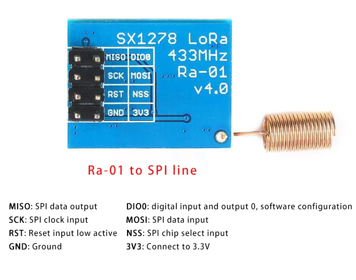
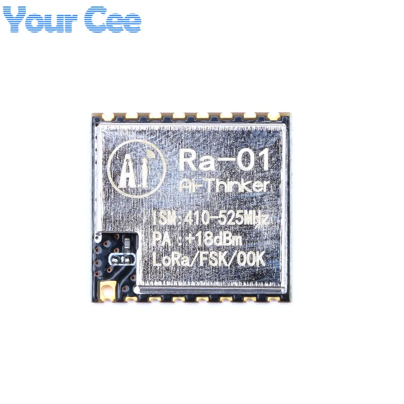
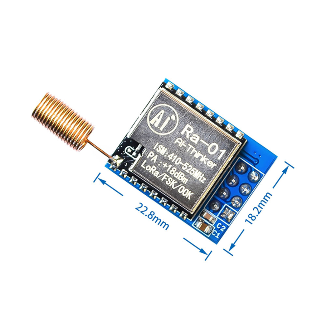
SX1261, SX1262, SX1268, SX1272, SX1276, SX1278
Elsa Jean Sperm
Hotshot Fucks A Young Slut Hard
My Fathers Secretary
Cum In Mouth Xhamster
Strapon Girl Solo