Inductively Coupled Plasma

🛑 👉🏻👉🏻👉🏻 INFORMATION AVAILABLE CLICK HERE👈🏻👈🏻👈🏻
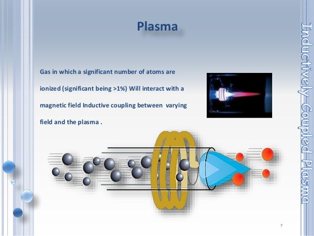
An inductively coupled plasma (ICP) or transformer coupled plasma (TCP)[1] is a type of plasma source in which the energy is supplied by electric currents which are produced by electromagnetic induction, that is, by time-varying magnetic fields.[2]
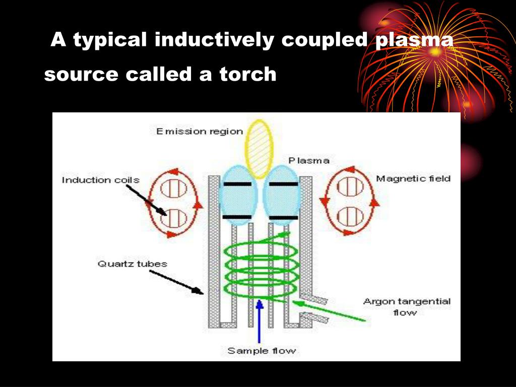
There are three types of ICP geometries: planar (Fig. 3 (a)), cylindrical [4] (Fig. 3 (b)), and half-toroidal (Fig. 3 (c)).[5]
In planar geometry, the electrode is a length of flat metal wound like a spiral (or coil). In cylindrical geometry, it is like a helical spring. In half-toroidal geometry, it is toroidal solenoid cut along its main diameter to two equal halves.
When a time-varying electric current is passed through the coil, it creates a time-varying magnetic field around it, with flux
where r is the distance to the center of coil (and of the quartz tube).
which corresponds to electric field strengths of
leading to the formation of the figure-8 electron trajectories[5] providing a plasma generation. The dependence on r suggests that the gas ion motion is most intense in the outer region of the flame, where the temperature is the greatest. In the real torch, the flame is cooled from the outside by the cooling gas, so the hottest outer part is at thermal equilibrium. There temperature reaches 5 000–6 000 K.[7] For more rigorous description, see Hamilton–Jacobi equation in electromagnetic fields.
The frequency of alternating current used in the RLC circuit which contains the coil usually 27–41 MHz. To induce plasma, a spark is produced at the electrodes at the gas outlet. Argon is one example of a commonly used rarefied gas. The high temperature of the plasma allows the determination of many elements, and in addition, for about 60 elements degree of ionization in the torch exceeds 90%. The ICP torch consumes ca. 1250–1550 W of power, but this depends on the elemental composition of the sample (due to different ionization energies).[7]
The ICPs have two operation modes, called capacitive (E) mode with low plasma density and inductive (H) mode with high plasma density, and E to H heating mode transition occurs with external inputs.[8]
Plasma electron temperatures can range between ~6,000 K and ~10,000 K (~6 eV - ~100 eV),[5] and are usually several orders of magnitude greater than the temperature of the neutral species. Argon ICP plasma discharge temperatures are typically ~5,500 to 6,500 K[9] and are therefore comparable to that reached at the surface (photosphere) of the sun (~4,500 K to ~6,000 K). ICP discharges are of relatively high electron density, on the order of 1015 cm−3. As a result, ICP discharges have wide applications where a high-density plasma (HDP) is needed.
Another benefit of ICP discharges is that they are relatively free of contamination, because the electrodes are completely outside the reaction chamber. By contrast, in a capacitively coupled plasma (CCP), the electrodes are often placed inside the reactor and are thus exposed to the plasma and subsequent reactive chemical species.
^ High density fluorocarbon etching of silicon in an inductively coupled plasma: Mechanism of etching through a thick steady state fluorocarbon layer Archived 2016-02-07 at the Wayback Machine T. E. F. M. Standaert, M. Schaepkens, N. R. Rueger, P. G. M. Sebel, and G. S. Oehrleinc
^ A. Montaser and D. W. Golightly, eds. (1992). Inductively Coupled Plasmas in Analytical Atomic Spectrometry. VCH Publishers, Inc., New York.CS1 maint: extra text: authors list (link)
^ Lajunen, L. H. J.; Perämäki, P. (2004). Spectrochemical Analysis by Atomic Absorption and Emission (2 ed.). Cambridge: RSC Publishing. p. 205. ISBN 978-0-85404-624-9.
^ Pascal Chambert and Nicholas Braithwaite (2011). Physics of Radio-Frequency Plasmas. Cambridge University Press, Cambridge. pp. 219–259. ISBN 978-0521-76300-4.
^ a b c Shun'ko, Evgeny V.; Stevenson, David E.; Belkin, Veniamin S. (2014). "Inductively Coupling Plasma Reactor With Plasma Electron Energy Controllable in the Range From ~6 to ~100 eV". IEEE Transactions on Plasma Science. 42 (3): 774–785. Bibcode:2014ITPS...42..774S. doi:10.1109/TPS.2014.2299954. ISSN 0093-3813. S2CID 34765246.
^ Бабушкин, А. А.; Бажулин, П. А.; Королёв, Ф. А.; Левшин, Л. В.; Прокофьев, В. К.; Стриганов, А. Р. (1962). "Эмиссионный спектральный анализ". In Гольденберг, Г. С. (ed.). Методы спектрального анализа. Москва: Издательство МГУ. p. 58.
^ a b Dunnivant, F. M.; Ginsbach, J. W. (2017). Flame Atomic Absorbance and Emission Spectrometry and Inductively Coupled Plasma — Mass Spectrometry. Whitman College. Retrieved 10 January 2018.
^ Hyo-Chang Lee (2018) Review of inductively coupled plasmas: Nano-applications and bistable hysteresis physics 5 011108 https://doi.org/10.1063/1.5012001
^ Cornelis, RITA; Nordberg, MONICA (2007). "CHAPTER 2 - General Chemistry, Sampling, Analytical Methods, and Speciation**Partly based on Chapter 2: General chemistry of metals by V. Vouk and Chapter 3: Sampling and analytical methods by T. J. Kneip and L. Friberg in Friberg et al. (1986).". Handbook on the Toxicology of Metals (Third ed.). Academic Press. pp. 11–38. doi:10.1016/B978-012369413-3/50057-4. ISBN 9780123694133.
Content is available under CC BY-SA 3.0 unless otherwise noted.
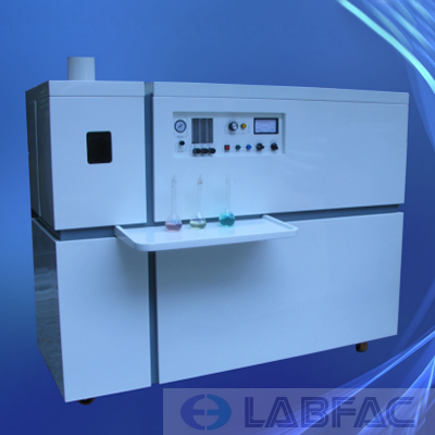
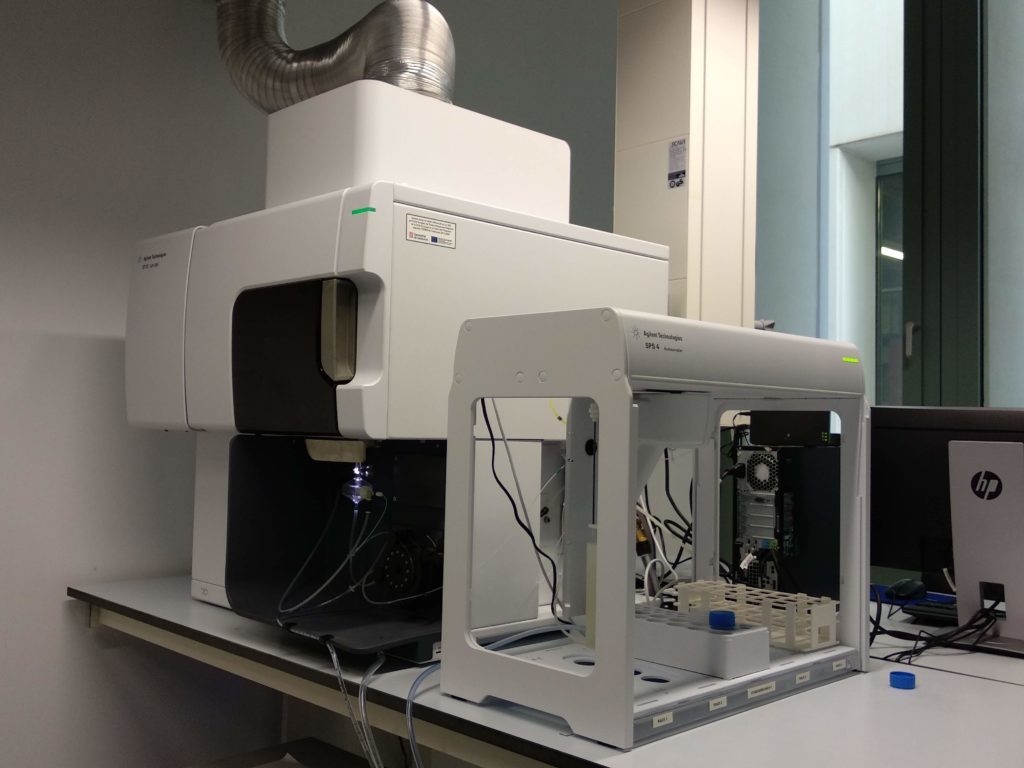
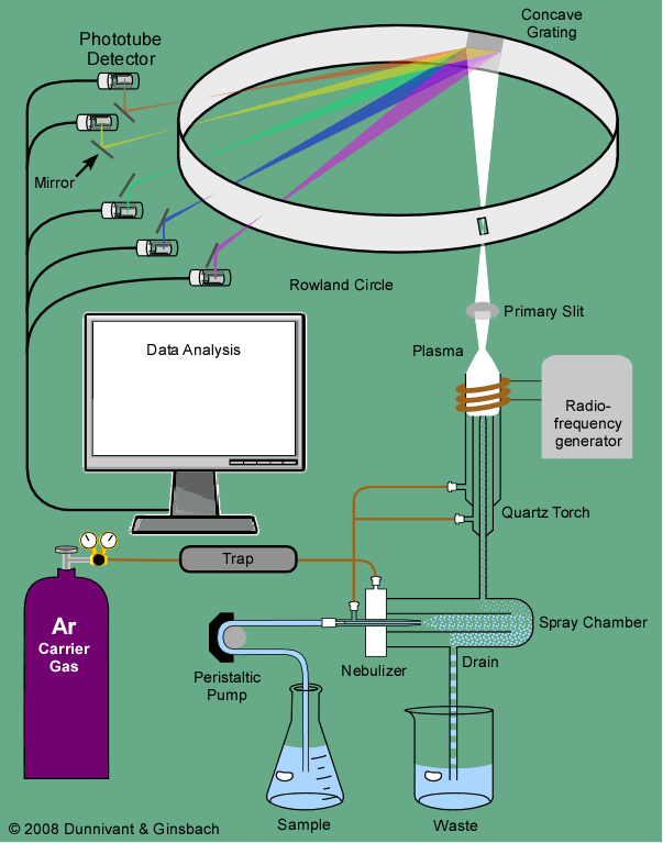
ICP is an atmospheric pressure ionization method, but unlike the previously mentioned atmospheric pressure ionization methods (ESI, APCI, and APPI), ICP is a hard ionization method, which results in complete sample atomization during sample ionization. An ICP source consists of a sample introduction system (nebulizer and spray chamber that provides the means by which the sample is transmitted into the instrument), an ICP torch, and a radio frequency (RF) coil for the generation of argon plasma, which serves as the ion source, and an interface, which connects the source to the mass spectrometer. In the clinical laboratory, ICP is commonly used for trace element analysis. Among the advantages of ICP are a wide dynamic range and the ability to detect elements at a level of parts per trillion.
URL: https://www.sciencedirect.com/science/article/pii/B9780128154991000107
The ICP–MS is a multielement analysis tool ideally suited for direct coupling with FFF. The ICP torch is capable of vaporizing and ionizing particles in the eluent up to ∼10 μm, and the plasma is then fed into an MS for simultaneous detection of many elements. Quadripole, mass-sector, and time of flight MSs are now available, depending on the sensitivity, mass resolution, and response time required. FFF–ICP–MS yields element-based size distributions. Other element detection systems that have been used include ICP–AESs, electrothermal atomic absorption spectrometers, and very recently laser-induced breakdown spectrometers.
URL: https://www.sciencedirect.com/science/article/pii/B0123693977001515
Inductively coupled plasma (ICP) excitation has revolutionized the field of emission spectroscopy, providing the analyst with a powerful multielement technique with good sensitivity for cadmium at 214.440 or 226.502 nm. Food and food products can be prepared for ICP analysis by either wet oxidation or dry ashing and samples with a wide range of elemental concentrations can usually be handled without the need to dilute or concentrate, since the ICP has a fairly large dynamic range. The current qualities of ICP – high speed, low detection limits (less than 0.01 mg kg−1 for cadmium), and excellent instrument stability – make this technology attractive for a wide range of analytical applications.
ICP-AES is used preferentially due to the possibility of handling a wide range of samples with minimum interference and of quantifying many of the metals, reducing analysis time, and providing a more sensitive determination of refractory elements. The potential of inductively coupled plasma mass spectrometry (ICP-MS) is affected by polyatomic interferences for some mineral elements that can be overcome by different sample introduction methods (hydride generation, flow injection, slurry nebulization) or separating procedures with chelating resins.
URL: https://www.sciencedirect.com/science/article/pii/B012227055X001425
Gregory P. Holmes-Hampton, ... Tracey A. Rouault, in Methods in Enzymology, 2014
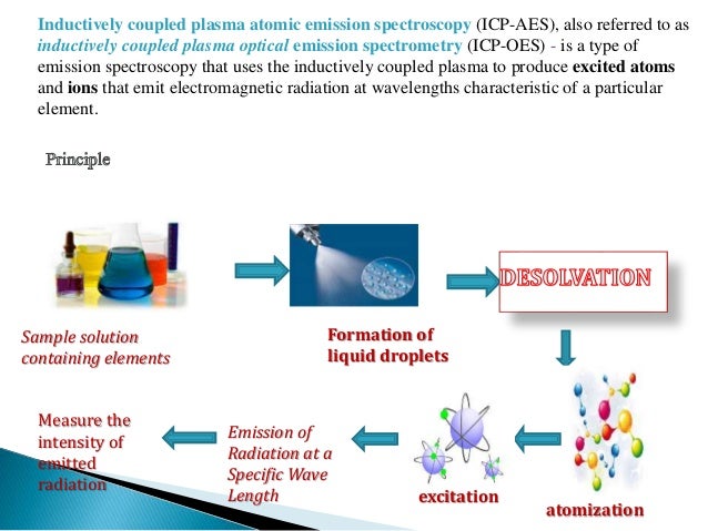
ICP-OES, also referred to as ICP-AES (atomic emission spectroscopy), utilizes a plasma torch, a device that causes gas to ionize and become electrically conductive in a state known as plasma. This plasma torch burns at ~ 7000 K, much hotter than the flame in a traditional FAAS setup (~ 2100–2700 K). Passing the argon gas through a magnetic coil and then applying a spark seeds the plasma by atomizing a population of the argon molecules. These charged molecules then have inelastic collisions with the neutral argon that propagates the plasma torch, which depends on the generation of a high-frequency electric current produced by electromagnetic induction known as inductive coupling. The torch will remain lit as long as the magnetic field is present to encourage the movement of the atomized particles of argon. The sample is then introduced as an aerosol via a nebulizer as in AAS. The much higher temperature of the torch in ICP leads to the atomization of essentially all sample molecules, which is not true for AAS.
Once the plasma torch has atomized the sample, the molecules are in an excited state. A detector then measures the light emitted by the sample as it returns to a ground state to determine which elements are present. Compared to AAS, ICP-OES is able to quickly detect many elements (~ 60 per minute, provided you have collected standard curves for these elements), and the instrument's detector determines this rate. ICP-OES also features a much larger dynamic range than AAS, meaning that less sample manipulation is necessary. The biggest discrepancy comparing ICP-OES and AAS is the higher price associated with the purchase of an ICP-OES instrument.
URL: https://www.sciencedirect.com/science/article/pii/B9780128014158000151
Inductively coupled plasma (ICP) sources couple radio frequency energy to an Ar gas stream. The RF energy completely ionizes the argon gas to generate a high-temperature plasma that can effectively ionize elements with very high first ionization potentials. The spread in the kinetic energy of the ions is considerably greater than in the thermal ionization or electron impact ion sources (~ 25 eV vs. ~ 2 eV) and the mass spectrometer with the ICP source requires energy focusing of the ion beam prior to mass separation by the magnetic sector. In addition to the energy filters, isotope ratio mass spectrometers with ICP ion sources have higher mass resolution in order to separate the masses of an element from isobaric interferences. For example, in the measurement of iron isotopes (54Fe, 56Fe, 57Fe, and 58Fe), it is necessary to optically resolve 56Fe+ from the large 40Ar16O+ ion beam. Thus, ICP mass spectrometers are equipped with adjustable entrance slits, which can be changed to achieve the optimum resolution and sensitivity for a particular element. ICP-based mass spectrometers designed for high precision isotope abundance measurements have multiple collectors for simultaneous collection of all isotopic ion currents of interest. As with electron impact and thermal ionization mass spectrometers, the measurement of the relative amounts of isotopes is independent of the fluctuations in the ionization of the sample. Despite the high precision (i.e. repeatability) of the isotope amount ratios measured by the ICP mass spectrometer, the high mass bias (up to several percent per mass unit) means that the ratios are inaccurate. The mass bias arises at the sample and skimmer cones, which form the interface between the plasma torch and the high vacuum of the mass analyzer. Ions of lighter masses are deflected by the high space charge that accumulates in this region. Thus, the ion beam transmitted through the instrument is relatively depleted in the lighter isotopes. The normalization of the measured isotope amount ratios must be done in order to generate meaningful results as the mass bias of the instrument can vary from day-to-day, from element-to-element, and depending on the chemical matrix of the solution being aspirated. Several normalization strategies are employed, including internal normalization using enriched isotopes of the element being measured, the addition of elemental spike of similar mass to the isotopes of interest, or sample-standard bracketing, which is a similar method employed for the calibration of isotope amount ratio measurements made by electron impact ion sources. Unlike the thermal ionization mass spectrometer, the mass bias of the ICP instrument remains relatively stable during the measurement of a sample, which may last for 10–20 minutes. Despite these challenges, the multiple collector inductively coupled plasma isotope ratio mass spectrometer is proving capable of revealing subtle differences in the isotopic abundances of many elements that were previously thought to have uniform terrestrial isotopic composition. This information has resulted in the redefinition of the atomic weights for elements such as Fe and Cu to reflect the variability of the relative amounts of the isotopes in terrestrial reservoirs.
Typically, the liquid analyte is aspirated by a nebulizer and introduced through a spray chamber into the Ar-plasma torch. A measurement session may require 1–3 ml of a solution with an elemental concentration of a few hundred parts per billion.
URL: https://www.sciencedirect.com/science/article/pii/B9780124095472052434
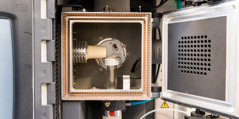
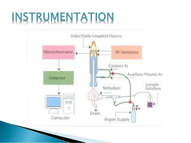
ICP sources have brought about a revolution in multielement analysis. ICPs are generated from radiofrequency (RF) magnetic fields induced by a water- or air-cooled copper coil looped around a quartz tube. The RF magnetic field oscillates at 27.12 or 40.68 MHz, at incident powers ranging from 0.5 to 2.5 kW. Higher powers are usually applied when organic solvents are aspirated. Argon gas flows through a torch, which consists of three concentric tubes usually constructed from fused silica. The plasma is initiated by seeding the argon stream with electrons provided from a Tesla coil. The electrons, detached from the argon atoms, collide with further argon atoms and populate the coil region with positive and negative charges. Because of the magnetic field, the particles flow in a closed annular path. Due to the conductance of the gases in the coil region, the charged particles are heated by inductive coupling to a temperature equaling the ionization temperature of the support gases ∼−7000–8000 K in the case of argon. A chain reaction of collisional ionization occurs, resulting in the formation of the ICP. In practice, the plasma impedance is monitored along with the tube grid current, grid voltage, plate current, and voltage. These data are fed back to a loop to control the plasma power. The configuration of an ICP-AES system is shown in Figure 4.
Figure 4. Schematic of an inductively coupled plasma source for atomic emission spectrometry.
URL: https://www.sciencedirect.com/science/article/pii/B0123693977000297
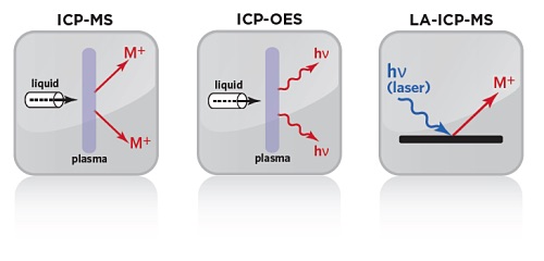
Inductively coupled plasmas either combined with atomic emission spectrometers (ICP–AES) or mass spectrometers (ICP–MS) where samples are excited using a high-temperature gaseous plasma can be used for elemental analysis. Since the development of ICPs, most applications have required digestion of solid samples with heat and/or strong acids. The coupling of laser-ablation (LA) with ICP–MS has resulted in the development of extremely sensitive microprobes capable of determining most elements of the periodic table. Another advantage of the technique is that LA–ICP–MS is point specific, that is, only the area ablated is subject to analysis. As a result, LA–ICP–MS has become one of the most exciting new fields of research in materials science in general.
URL: https://www.sciencedirect.com/science/article/pii/B0123693977002016
Inductively coupled plasmas were developed in the early 1960s [2]. They are flame-like discharges that can reach up to 10,000 K in temperature and are formed in a stream of argon, though other gases have been used, flowing through an electromagnetic field.
Typically in an ICP the gas flows into three concentric tubes. These tubes are assembled together in what is commonly referred to as the plasma torch (Fig. 12.1). The flowing gas in the outer tube, which is typically in the range of 13–17 L/min, is often referred to as the cool gas and its primary role is to ensure that the high temperature of the plasma does not melt the torch. In addition to this primary function, the cool gas also plays a role in giving the plasma its distinct shape. The flowing gas in the central tube, which is usually in the range of 1 L/min, is commonly referred to as the plasma gas and is actually the gas that gets ionised to form the plasma. Finally, the gas flowing in the innermost ring is called the carrier gas and is used to punch the plasma whilst carrying an aerosol or particulate form of the sample to be analysed.
Fig. 12.1. A schematic of the drawing of an ICP torch.
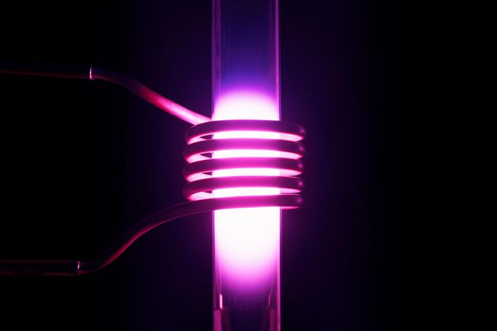
As shown in Fig. 12.1, one end of the torch is encircled by a coil. A radio-frequency current flows through the coil to create an electromagnetic field in which the argon flows. To light the plasma a high voltage discharge (spark) is passed through the argon. When passing through the electromagnetic field, electrons from the discharge gain energy. Some of these electrons transfer this energy through collisions to the argon atoms in the gas thereby ionising them. This will create sets of ion-electron pairs that are in turn energised in the presence of the electromagnetic field and are made to participate in this cascading method of energy transfer from the coil to the gas. The outcome of this cascade is the formation of a steady-state plasma that is maintained as long as the radio-frequency current is upheld at a sufficient intensity and the gas flow is preserved. The fireball-like argon plasma is characterised by a bluish white emission which is a combination of emissions from the line spectrum of atomic argon and the continuous spectrum of ion-electron recombinations taking place within the plasma.
When formed, the plasma has the shape of a prolate spheroid, and the rapid expansion and acceleration of the argon gas inside it makes it difficult for sample introduction. However, by punching a central channel inside the plasma, its shape is changed into an annular “doughnut” form with the outer “plasma” gas virtually shielding the central “carrier” gas and with very little mixing taking place between the two. As a result, samples can be introduced in a gaseous or aerosol form along this central channel without significantly disturbing the plasma or changing its composition. However, during its stay in this channel, the sample will be efficiently desolvated, atomised, excited and ionised. Hence any chemical species injected into the pla
Beauty Boobs
Celebrity Porn Scandal
Sex Celebrity Net Porno
Dick Stick
Putalocura Com Bukkake
Inductively coupled plasma - Wikipedia
Inductively Coupled Plasma - an overview | ScienceDirect ...
Inductively Coupled Plasma Mass Spectrometry (ICP-MS ...
Inductively coupled plasma mass spectrometry - Wikipedia
Inductively Coupled Plasma (ICP) - Chemistry LibreTexts
Inductively coupled plasma - Simple English Wikipedia, the ...
Inductively Coupled Plasma


.jpg)