Hole Stop

👉🏻👉🏻👉🏻 ALL INFORMATION CLICK HERE 👈🏻👈🏻👈🏻
Loading [MathJax]/extensions/MathZoom.js
Volume 6, Issue 3 , September 2015 , Pages 987-999
About cracks, dunce caps and a new way to stop cracks
Fatigue Fract Eng Mater Struct , 32 ( 2009 ) , pp. 484 - 492
On the prediction of the residual fatigue life of cracked structures repaired by the stop-hole method
Int J Fatigue , 32 ( 2010 ) , pp. 670 - 677
A crack-growth arresting technique in aluminum alloy
Eng Failure Anal , 15 ( 2008 ) , pp. 302 - 310
Numerical analysis of the influence of stopping holes in the crack growth
J Aero Space Sci Technol JAST , 4 ( 1 ) ( March 2007 ) , pp. 9 - 16
Investigate the delay of crack using stop drilled holes on mild steel
Faculty of Mechanical Engineering, Universiti Malaysia Pahang ( November 2009 )
Stress concentration at stop-drilled holes and additional holes
Eng Failure Anal , 15 ( 2008 ) , pp. 810 - 819
Stop drilling procedure for fatigue life improvement
Int J Fatigue , 26 ( 12 ) ( December 2004 ) , pp. 1333 - 1339
Crack-growth arrest by redirecting crack growth by drilling stop holes and inserting pins into them
Eng Failure Anal , 16 ( 2009 ) , pp. 475 - 483
R.J. Callinan , C.H. Wang , S. Sanderson
Analysis of fatigue crack growth from cold-expanded/interference fitted stop drilled holes , Defense Science and Technology Organization , Australia ( July 1998 )
Fatigue at notches and the local strain and fracture mechanics approaches
C.W. Smith (Ed.) , Fracture mechanics, ASTM STP 677 , American Society for Testing and Materials , Philadelphia ( 1979 ) , pp. 247 - 273
A stress strain function for the fatigue of metals
J Mater , 5 ( 4 ) ( 1954 ) , pp. 767 - 778
Assessment of low cycle fatigue strength of notched component
Mater Des , 27 ( 2 ) ( 2006 ) , pp. 132 - 140
Effect of welded stiffeners on crack growth rate
Ship Structure Committee , Washington, USA ( 2000 )
On blunting the crack tip through hole-drilling
Alexandria Eng J , 42 ( 3 ) ( 2003 ) , pp. 347 - 355
Structural Eng. Dept., Faculty of Eng., Alexandria University, Alexandria, Egypt
Elementary engineering fracture mechanics
( 4th ed. ) , Kluwer Academic Press , Boston ( 1991 )
Copyright © 2015 Faculty of Engineering, Ain Shams University. Production and hosting by Elsevier B.V.
Composite Structures, Volume 178, 2017, pp. 119-134
Ain Shams Engineering Journal, Volume 6, Issue 3, 2015, pp. 1001-1008
Theoretical and Applied Fracture Mechanics, Volume 108, 2020, Article 102643
In the present study, the stop-hole method was investigated with creating a noncircular hole. The aim of the present work was to obtain an optimum stop hole shape that gives maximum fatigue crack initiation life by using finite element program. It was found that the fatigue life obtained by using the optimum hole shape ranges from 2 to 9 times the fatigue life obtained by using the circular holes. It was found that the optimum hole shape increased the initial fatigue life for all specimens used. Opposite to the traditional stress concentration factor minimization problem where the nominal area remains constant during optimization, here it is allowed to vary nominal area using design variables resulting in decreasing of the nominal stress in addition to decreasing of the stress concentration factor. This leads to higher fatigue life compared to previous studies.
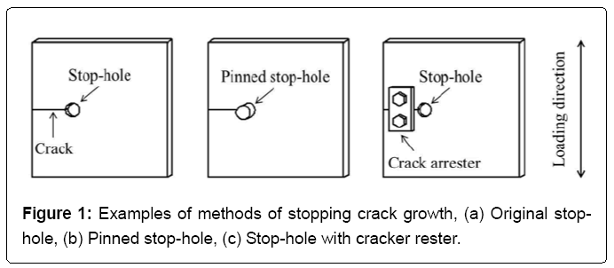
The effect of a geometrical discontinuity such as notch is to intensify the magnitude of the nominal stress in the vicinity of the discontinuity. The localized stresses may cause the metal in that neighborhood to undergo plastic deformation. Because the nominal stresses are elastic, an elastic-stress field surrounds the zone of plastically deformed metal in the vicinity of stress concentration. A fatigue crack initiates more rapidly as the magnitude of the local cyclic-plastic deformation increases. That is, when the material in the vicinity of the notch tip is subjected to stress ranges approximately equal to or larger than the yield stress of the material, the plastic deformation causes the material to deform along slip planes that coincide with maximum shear stress, which results in slip steps on the surfaces of the notch. These slip steps act as new stress raisers that become the nucleation sites for fatigue cracks which initiate along the maximum shear planes and propagate normal to the maximum tensile stress component [1] . Crack arresting methods have different techniques, such as method of tensile triangles which had been introduced by Mattheck et al. [2] for optimizing the shape of notches by adding material at overloaded regions but also to remove unloaded material from an oversized design proposal. Other crack arresting methods, such as branching of crack direction are introduced by Shabara [3] and this method could reduce crack growth rate or even stop it for a period of time. Other researches aimed to reduce the effect of stress raisers to increase crack initiation life, by using a stop hole method as Wua et al. [4] . Some researchers investigated arresting crack initiation at stop-drilled hole by drilling ancillary holes around the principle stop hole Murdani et al. [5] . Fatigue crack initiation life prediction had been evaluated by Khoshravan and Hamidi [6] by employing classical strain life concepts properly modified by short crack theory to model the stop-hole effect and investigated the best location of stop hole and its diameter. Shah [7] studied the effect of drilling holes in the vicinity of crack tips on the direction of the crack, time taken for the specimen to fracture, and the breaking load of the specimen. Others investigated the stress concentration factors for the stop drilled holes [8] , while others investigated how the stop drilling procedure improved the crack initiation life and the total fatigue life [9] . Some were interested in investigating the efficiency of crack arresting by drilling a stop-hole on riveted girders theoretically and by full-scale fatigue test series [10] . Investigation of The global optimum shape was similar to the plastic zone created around crack tip that means by drilling optimum shape, it removes all damage materials, leaving material in virgin stat, so initial fatigue life increases many times. Inserting pins into holes drilled in the vicinity of the crack tips or the cold expanded hole had been studied by Makabe et al. [11] , who found that compressive residual stress, which occurred by inserting pins, was more effective to retard the crack growth than reducing the stress concentration around initial crack tips by drilling holes.
Based on the previous literature review, it was found that almost all researches deal with arresting the fatigue crack with drilling a circular hole. The effect of changing the hole shape has not been studied yet. Therefore the objective of this study was to introduce a new method for improving the crack initiation life by stopping crack growth with modifying the hole shape using optimization technique. The optimum shape of stop hole at the crack tip will maximize the crack initiation life of a precracked component subjected to fatigue loading without decreasing nominal area of specimen.
Finite Element Method using ANSYS software package for nonlinear static analysis.
Shape optimization of the analyzed hole using ANSYS
The minimum strain energy resulted from optimization step is input to MATLAB to solve nonlinear Smith Watson and Topper (SWT) equation to get maximum initial fatigue life.
The flowchart of hole shape optimization method is given in Fig. 1 .
Figure 1 . Flowchart of hole shape optimization method.
The studied model is rectangular block, with 80 mm length, 40 mm width, and 10 mm thickness. The circular edge notch has a radius, r , of 1.5 mm, and propagated sharp crack length, a , of 6 mm. The radius R , of the hole at the crack tip equals 1 mm [12] , as illustrated in Fig. 2 .
A two-dimensional simulation finite element model using ANSYS software package was used. The material used in this analysis was RQC-100 steel with mechanical properties shown in Table 1 . In this model it was assumed that the material is homogeneous and isotropic, i.e., without imperfections or damages.
Table 1 . RQC-100 steel mechanical properties [12] .
Eight-node plane element (Plane 82) is adopted, because these quadrilateral elements can deal with problems when analyzing about a point, such as the crack tip. A very fine mesh with element size equals 0.1 mm has been utilized around the area of interest (the crack stop hole edge) and a relatively courser mesh far from the stop hole edge has been used in order to save simulation time. The total number of nodes, and elements, and DOF are shown in Table 2 . The finite element mesh is illustrated in Fig. 3 .
Table 2 . Total number of nodes, elements, and DOF for fine mesh and course mesh.
Figure 3 . Fine mesh around hole and courser mesh far from the hole.
Due to the symmetry of the model, only half of the part was modeled to increase the efficiency of the optimization procedure as in Fig 3 . Due to the high stress and strain gradients around the hole edge, it is critical to choose elastic–plastic nonlinear static analysis type with small displacement to capture these gradients. Methods for analysis in that case are usually based on the relation between deformations, stresses, and number of loading cycles. Symmetrical constraints were placed on the specimen along the axis of symmetry. As along this boundary, the elements cannot move vertically or rotate, while along the notch and hole, the elements could move freely because it was not attached to the symmetric plane. All constrains and loading conditions are shown in Fig. 4 .
Figure 4 . Constrains and loading conditions.
Applied stress is a uniaxial cyclic stress with stress ratio equals, −1 and peak value, 90 MP at the model top line as illustrated in Fig. 4 . Each load step occurred after one unit of time. The load steps were also broken up into substeps in which a fraction of the load was applied over an interval of time between the maximum and minimum loads. When solution is done, the maximum local stresses and strains are obtained at the hole surface. These values of stresses and strains are used to calculate crack initiation life using Smith Watson and Topper (SWT) equation [13] , which can be solved using MATLAB software.
An optimization program was carried out using ANSYS software in order to find the optimum shape of the stop hole. The objective function of this research was to obtain the optimum hole shape which is corresponding to the minimum value of strain energy ( σ max ɛ ) in order to maximize the crack initiation life ( 2N f ). To evaluate objective, the strain life method is usually used to determine the number of cycles required for the fatigue crack initiation, where it is assumed that the crack is initiated at the point of the largest stresses in the material. To determine crack initiation life, Smith Watson and Topper (SWT) equation (1) can be used as follows: (1) σ max Δ ε 2 = ( σ f ′ ) 2 E ( 2 N f ) 2 b + σ f ′ ε f ′ ( 2 N f ) b + c where 2 N f is number of reversals up to crack initiation, ɛ a is total strain amplitude, σ max is the maximum equivalent Von Mises stress, b is the fatigue strength exponent, σ f ′ is the fatigue strength coefficient, ε f ′ is the fatigue ductility coefficient and, c is the fatigue ductility exponent. Material characteristics of RQC-100 steel [14] under cyclic loading are: b = −0.07; σ f ′ = 1240 MPa ; ε f ′ = 066 ; and c = −0.69.
FE program results showed that the maximum Von Mises stress was maximum at the stop hole edge which agreed with Ref. [15] results. Because fatigue cracking normally occurs at the surface, Von Mises stress is a more appropriate criterion.
By using MATLAB software, relationship between strain energy and initial fatigue life for RQC-100 steel is plotted as illustrated in Fig. 5 .
Figure 5 . The objective function for the optimization program is to minimize strain energy and to maximize the crack initiation life.
The curve showed that min ( σ max ε a ) → max ( 2 N f )
The geometric representation of the designed boundary for optimization technique was chosen so that an effective geometry could be represented by the least possible amount of parameters. Therefore, half of the hole was modeled by a spline connecting 7 key points having polar coordinates ( R , ɵ ). The design variables are chosen to be the radial coordinates of these key points as R 1, R 2, R 3, R 4, R 5, R 6, and R 7. The angles, ɵ , of the key points are changed from 0° to 178° with a constant increment value equals 30°. These angles are kept constant during optimization. The design variables are shown in Fig. 6 .
The initial values of design variables were initially started from the circular hole shape (as illustrated in Fig 6 ). The initial value for R 1 to R 7 was 1 mm. These variables were arranged from R 1 at hole edge, up to R 7 toward free edge of the specimen. Design variables were allowed to change within the range of 0.5–1.5 mm. In the ANSYS program, several different optimization tools and methods are available. In this work the first order method was chosen because, this method uses derivative information, of gradients of the dependent variables with respect to the design variables. It is highly accurate and works well for problems having dependent variables that vary widely over a wide range of design space. However, this method can be computationally intense.
After optimization process was completed, the values of design variables were changed to the values listed in Table 3 . These values define the optimum hole shape which accomplish the objective function as illustrated in Table 3 .
Table 3 . Optimized design variables that define the optimum hole shape.
Table 3 indicates that the optimum hole shape does not increase the size of initial circular hole, it just reshapes it as illustrated in Fig. 7 . This indication has a significant importance for nominal stress and stress concentration as will be investigated in detail later.
Figure 7 . Comparison between optimum hole size, and circular hole size.
Initial fatigue life was calculated for both of circular and optimum hole shapes. It is found that initial fatigue life using circular hole was 868,600 cycles, while using optimum hole shape increases initial fatigue life to 5,525,000 cycles as illustrated in Fig. 8 .
Figure 8 . Initial life using optimum hole shape and initial life using circular hole shape.
The optimum hole shape reduces Von Mises stress, and VonMises strain at hole edge. The maximum reduction of stress, and strain occurred at hole edge, which is most probably the location for crack initiation, as illustrated in Figure 9 , Figure 10 respectively. The high stress gradient close to the hole was reduced, resulting in a better stress distribution as illustrated in Fig. 11 .
Figure 9 . VonMises stress using optimum hole shape and using circular hole shape.
Figure 10 . Von Mises strain using optimum hole shape and using circular hole shape.
Figure 11 . Stress and strain distribution for (a) optimum hole shape and (b) circular hole shape.
The model geometry has four configuration parameters: height h, width W , initial crack length a , and the initial stop hole radius R as shown in Fig. 12 . R will be changed during optimization process; however its initial value can be obtained using previous researches [16] , [17] , [18] , [19] . It is found necessary to get a global optimum hole shape [it is called global to point out that it is suitable for all geometries]. If succeeded, it will help the engineers to use it directly in practice, much like the use of the stop hole size found in the literature. In order to validate this optimum shape, it is important to study the effect of using this optimum shape on fatigue life for different specimen geometries. According to load direction for this model the most important configuration parameter is the width W . Therefore, the other two parameters, a and h will be normalized by W . The ratio, a / W has a significant importance on stress distribution, [20] . a / W is varied from 0.1 to 0.3. For every value of a / W ratio, h / W values are examined to get its effect on optimization results as illustrated in Fig. 12 .
Figure 12 . (a) The most important geometrical parameters and (b) flowchart of geometries which have been tested in this study.
Each case has its own optimization program and produces its own optimum hole shape. Figure 13 , Figure 14 respectively illustrate the relation between the maximum stresses and strains obtained at the crack stop hole for different values of h / W . These figures illustrate the comparison between the stresses and strains using circular hole, the optimum hole shape, and the optimum shape obtained for each h / W value. It is found that the global optimum hole shape results are close to each h / W optimization result. That signifies the ability of applying optimum hole shape for all cases and getting nearly optimum results for each geometry. That has a significant importance in practical field.
Figure 13 . Comparison of maximum stress at hole edge for circular hole, optimum hole shape, and hole shape obtained from optimization results for each h / W geometry.
Figure 14 . Comparison of maximum strain at hole edge for circular hole, optimum hole shape, and hole shape obtained from optimization results for each h / W geometry.
The effect of changing the h / W values on the initial fatigue life is illustrated in Figure 15 , Figure 16 , Figure 17 for a / W equals 0.1, 0.2, and 0.3, respectively. These figures illustrate the initial fatigue life when using circular hole, global optimum hole, and the optimum hole shape obtained for each h / W geometry. It is noticed that the values of initial fatigue life using global optimum hole shape for all cases is nearly similar to those optimum shape obtained for each h / W .
Figure 15 . Initial fatigue life at hole edge for circular hole, optimum hole shape, and hole shape obtained from optimization results for each h / W geometry at a / W = 0.1.
Figure 16 . Initial fatigue life at hole edge for circular hole, optimum hole shape, and hole shape obtained from optimization results for each h / W geometry at a / W = 0.2.
Figure 17 . Initial fatigue life at hole edge for circular hole, optimum hole shape, and hole shape obtained from optimization results for each h / W geometry at a / W = 0.3.
It was found that the optimum shape gave results better than circular hole up to 9 times. It is found from all previous Figures that increasing h/W values increased the fatigue life, while increasing a / W v
https://www.sciencedirect.com/science/article/pii/S2090447915000362
https://slovar-vocab.com/english-russian/scientific-technical-vocab/stop-hole-4433296.html
Real Homemade Granny Nude
Muslim Boy Girl
Endless Night Club Xxx
New crack stop hole shape using structural optimizing ...
STOP HOLE перевод с английского на русский, translation ...
stop hole - это... Что такое stop hole?
Cheap Hole Stop, Wholesale Hole Stop, Hole Stop Cheap ...
How To: Use 2-Hole Cord Stops - YouTube
Stop the hole, stop UV - Slogan
Law of holes - Wikipedia
Say Goodbye to Tiny Holes in your Shirts With Holé
Hole.io
Stoping - Wikipedia
Hole Stop