Hole Plate

💣 👉🏻👉🏻👉🏻 ALL INFORMATION CLICK HERE 👈🏻👈🏻👈🏻
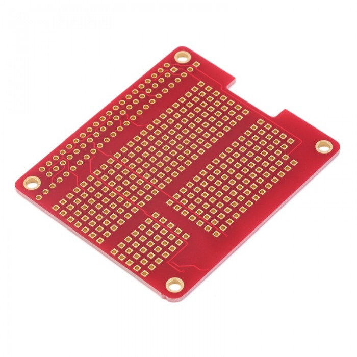
Electroless copper plating is used to plate holes to make PTHs and vias. While drilled holes are being plated some of the external surfaces are also plated. The thickness of the plating is typically 20 to 100 microinches both in the holes and in the surfaces depending on the board manufacturer’s processes (IPC-2221A, Table 4-3; Coombs 2001, p. 28.8).
Later in the fabrication process other plating processes are used to “finish” the board. After finishing processes are completed, the external surfaces of a PCB can be much thicker, but the wall thickness of a PTH is usually 1 mil or less. Most of the time it does not enter into the drill size calculations unless the hole is very small (most finished hole sizes are 8 mils or larger), but the information is presented here for completeness. Table 4-5 shows the minimum PTH wall thickness as presented in the literature (IPC-2221A, Table 4-3).
Table 4-5. Minimum Electroless Plating Thicknesses (Surfaces and Holes)
Reference: IPC-2221A, Table 4-2 (partial data).
URL: https://www.sciencedirect.com/science/article/pii/B9780750689717000044
Electroless copper plating is used to plate holes to make PTHs and vias. While drilled holes are being plated some of the external surfaces are also plated. The thickness of the plating is typically 20–100 µin. both in the holes and in the surfaces depending on the board manufacturer’s processes (Coombs, 2001, p. 28.8; MIL-STD-275, Table 4-3).
Later in the fabrication process other plating processes are used to “finish” the board. After finishing processes are completed, the external surfaces of a PCB can be much thicker, but the wall thickness of a PTH is usually 1 mil (25 µm) or less. Most of the time, it does not enter into the drill size calculations unless the hole is very small (most finished hole sizes are 8 mil or larger), but the information is presented here for completeness. Table 4.5 shows the minimum PTH wall thickness as presented in the literature (MIL-STD-275, Table 4-3).
Table 4.5. Minimum electroless plating thicknesses (surfaces and holes).
Source: IPC-2221B, Table 4-2 (partial data).
URL: https://www.sciencedirect.com/science/article/pii/B9780128176849000047
Although the design of aeronautical structures necessitates the use of allowables taking into account the material dispersion (A and B values) to ensure the required level of confidence, the average values of the stiffness and strengths are used in the present study. Indeed, this study deals with the evaluation of the predictive capabilities of alternative strength analysis methods through comparisons with available test data.
Tensile tests on T700GC/M21 open-hole plates with 10 different stacking sequences have been performed. For all the specimens, the hole diameter is equal to 6.35 mm and the plate width-to-hole diameter ratio is fixed at five. Each test configuration has been repeated and only the average failure load is reported in this paper.
For the FCV method, the internal length ρ in tension has been identified on the 50/40/10 laminated perforated plate as explained in the Section 19.3.1. For the CC, the toughness of the 0° ply and of the [± 45°] sub-laminate have been identified on the 50/40/10 and 10/80/10 laminated perforated plates as explained in Section 19.4.2.
Figure 19.8 presents the comparison between the predicted ultimate failure loads, obtained with the two proposed alternative methods, on T700GC/M21 perforated plates with different stacking sequences subjected to uni-axial tensile loading and the available test results. The predictions of the FCV method agree with the experimental data on the other nine stacking sequences even for highly oriented (60/30/10) and disoriented (10/80/10) laminates because the different material non-linearities, especially the elastic non-linearity and the viscoelasticity, are taken into account. The predictions obtained with the CC method also agree with the experimental data for the oriented laminates. Nevertheless, the error increases for the disoriented laminates (higher than + 10%) because the material non-linearities, which are influent on the macroscopic behaviour for such disoriented stacking sequences, are neglected with the CC approach. Contrary to the FVC method, in which the internal length is constant, the nucleation length a* that is determined by the CC, varies as a function of the stacking sequence. Indeed, this length is a function of Lc (see Equation 19.9). It means that a* is large for low strength (in the case of the disoriented materials) and small for high strength (in the case of the oriented materials).
Figure 19.8. Comparison between predicted (FCV and CC methods) and measured normalised failure loads of T700GC/M21 laminated perforated plates, with different stacking sequences, subjected to uni-axial tensile loading (d = 6.35 mm and w/d = 5).
In this section, we look at the influence of the hole diameter on the strength of open-hole plates subjected to uni-axial tensile loading, the total thickness of the coupon remaining constant and the w/d ratio is fixed at 5. The variation of the hole diameter induces a modification of the stress gradient in the vicinity of the perforation. This test case is thus relevant to estimate the predictive capabilities of the proposed strength analysis methods.
From the experimental point of view, four different hole diameters have been tested for six different T700GC/M21 lay-ups (three oriented and three disoriented laminates). Each test has been repeated, and only the average failure loads are reported in Figure 19.9. For the two considered methods, the predicted macroscopic stress at failure, defined by the ultimate load at failure divided by the real section, are in good agreement with the available test results on oriented and disoriented open-hole plates with different hole diameters as illustrated in Figure 19.9.
Figure 19.9. Comparison between predicted (FCV and CC methods) and measured normalised macroscopic stress at failure of T700GC/M21 laminated oriented (a, b) and disoriented (c, d) perforated plates, with different hole diameters, subjected to uni-axial tensile loading (w/d = 5).
The predictions obtained with the two different simplified approaches are rather similar for the oriented laminates (Figure 19.9a and b) but become different for the disoriented laminates (Figure 19.9c and d), especially for the small diameters of hole, for the reasons mentioned in the previous section.
For the FCV method, the introduction of the dependence of the internal length to the radius of perforation (defined in Equation 19.5) allows obtaining accurate or reasonably conservative predictions, especially for 60/30/10 perforated laminates. It should be noted that the dependence of the internal length to the hole diameter, defined in Equation (19.9), is taken into account automatically with the CC approach, contrary to the FCV method.
Moreover, some experimental data on similar configurations can be found in the literature. Indeed, Camanho et al. (2007) have performed tests on IM7/8552 quasi-isotropic open-hole plates subjected to uni-axial tensile loading. Six different hole diameters have been considered (from 2 to 10 mm), whereas the w/d ratio remains constant at five.
For the FCV method, the internal length has been identified from tests performed on the open-hole plates with a hole diameter equal to 6 mm (closest configuration to that encountered in the aeronautical industry). For the CC approach, the fracture toughness has been determined using the compact tension test available in Camanho et al. (2012) and Tan (1988).
Figure 19.10 presents the comparisons between the predicted macroscopic stress at failure and test results on IM7/8552 quasi-isotropic open-hole plates with different hole diameters subjected to uni-axial tensile loadings. The predictions obtained with the two methods are in good agreement with experimental data and are rather similar, except for small diameters of hole (inferior to 3 mm). The CC approach seems to better match the experimental results than the FCV method, because the influence of the hole diameter on the internal length is not a priori fixed with the CC approach. The CC approach and the FCV method can thus be complementary. Indeed, the influence of the stress gradient on the internal length can be determined using the CC approach. The CC approach permits us to show that the internal length is not exactly a function of
r
. Finally, the FCV method could use the evolution of ρ as a function of r determined by the CC to predict the final failure of the open-hole plates for different configurations of perforation.
Figure 19.10. Comparison between predicted (FCV and CC methods) and measured (Camanho et al., 2007) macroscopic stress at failure of IM7/8552 quasi-isotropic perforated plates, with different hole diameters, subjected to uni-axial tensile loading (w/d = 5).
In this test case, the perforation diameter in the T700GC/M21 laminated open-hole plates remains constant at 6.35 mm, whereas the w/d ratio evolves from three to six. Figure 19.11 presents the comparison between the predicted macroscopic stresses at failure and the tensile test results. Six different stacking sequences have been investigated and each test configuration has been repeated. The predicted failure loads are consistent with the experimental data. Indeed, since the hole diameter is constant, the stress gradient near the hole remains unchanged. Therefore, the macroscopic stress at failure for large w/d ratios (superior to five) remains quasi-constant. Nevertheless, for small w/d ratios (less than four), the specimens are narrow and the influence of the free edges on the stress gradient around the hole can no more be neglected and induces a decrease in the macroscopic stress at failure. For small w/d ratios, the FCV method slightly overestimates the final failure because the edge effects are neglected by the analytical method, as reported in Figure 19.11a. This difficulty can be overcome by using the FE simulation to estimate the membrane loadings within the open-hole plate.
Figure 19.11. Comparison between predicted (FCV and CC methods) and measured normalised macroscopic stress at failure of T700GC/M21 laminated perforated plates, with different w/d ratios, subjected to uni-axial tensile loading (d = 6.35 mm).
The results obtained with the CC approach, reported in Figure 19.11b, are similar but tend to overestimate the failure stress in the case of disoriented laminates, for the reasons mentioned previously.
Figure 19.12 presents the comparison between the predicted ultimate failure loads, obtained with the FCV method, on T700GC/M21 perforated plates with three different stacking sequences and subjected to off-axis tensile loading and the test results. For all the perforated tested plates, the hole diameter is 6.35 mm and the w/d ratio is fixed at five. This kind of off-axis tensile tests permit us to obtain a more complex multi-axial stress field in the vicinity of the hole, whereas the experimental device remains the same. The predicted failure loads have been successfully compared with the experimental data, such as the failure pattern which evolves as a function of the off-axis angle. The maximal error is observed in the tensile test on oriented laminates with an off-axis angle evolving between 15° and 35°, where the in-plane shear stresses, in the most loaded plies in the fibre direction, attain high values. This point should be studied in further works. The present test case has not been treated with the CC approach because of meshing issues for this particular configuration of tests on open-hole plates. This test case will be considered in further works, because no fundamental limitation is encountered here with the CC approach.
Figure 19.12. Comparison between predicted (FCV method) and measured normalised failure loads of T700GC/M21 laminated perforated plates, with different stacking sequences, subjected to off-axis tensile loading (d = 6.35 mm and w/d = 5).
Finally, the proposed alternative strength analysis methods have been applied to T700GC/M21 open-hole plates subjected to uni-axial tensile loading with complex configurations of perforation and with unconventional stacking sequences, in order to determine its predictive capabilities. The width of the plates is w = 38 mm and the hole diameters are, respectively, d = 7.8 mm for the plates with two holes and d = 3.9 mm for the plates with four holes. For this test case, the membrane loadings have been determined with FE simulations for the FCV method because of the interaction between the stress gradient due to the free edges and the holes. Figure 19.13 presents the comparison between the predicted failure loads and the available test results. The tests have been performed at Onera, and only one sample for each configuration has been tested (Laurin et al., 2011). The observed failure mode is the fibre failure mode in tension for all the tested samples.
Figure 19.13. Comparison between predicted (FCV and CC methods) and measured failure loads of T700GC/M21 multi-perforated plates subjected to uni-axial tensile loading.
This test case is essential because it demonstrates that the proposed approach is able to predict accurately the final failure load of perforated plates with unconventional stacking sequences and complex configurations of perforation. Therefore, the present simplified methods could be used in an optimisation process or to generate a ‘virtual’ test database, contrary to the strength analysis methods used currently in design offices, such as the point stress method.
URL: https://www.sciencedirect.com/science/article/pii/B9780081003329000190
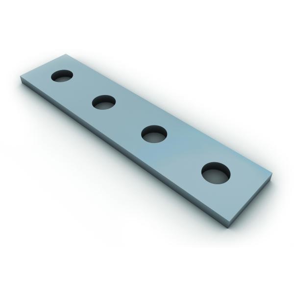
To demonstrate the nature of the squeeze-film damping of thick hole-plate, we consider a rectangular hole-plate with a length much larger than its width (i.e., b is much larger than a as shown in Fig. 3.3.2). Thus, Eq. (3.3.7) becomes one-dimensional.
Fig. 3.3.2. Geometries of a long rectangular hole-plate (holes are not shown)
With boundary conditions of P(±a)=0, the distribution of damping pressure is
The dependence of pressure distribution on the ratio of a/l is shown in Fig. 3.3.3, where the damping pressure has been normalized to Rl2.
Fig. 3.3.3. Dependence of normalized pressure distribution on a/l
We can learn from Eq. (3.3.12) or Fig. 3.3.3 that the larger the ratio a/l, the larger the effect of hole on damping and the smaller the border effect of the plate, and vice verse. Note that the maximum pressure at centre, P(0), increases with l for a constant a. This might not be easily seen as the pressure in Fig. 3.3.3 have been normalized by Rl2.
Now let us consider two extreme conditions. If the holes are very thin and the plate is very thick so that the attenuation length l is much larger than the half width a, Eq. (3.3.12) returns to
This is the same result as given by Eq. (3.2.13) in §3.2.2 (with B=2a).
To another extreme, if the plate is very thin so that a≫l, Eq. (3.3.12) shows that the pressure for most area of the plate has a constant value of
This equation agrees with Eq. (3.2.39) for the damping pressure of an infinite thin hole-plates. The above results for the two extremes also justify the modified Reynolds' equation.
Generally, l is indeed much smaller than a, but has a finite value so that its effect on the damping pressure in the areas near the borders cannot be neglected. In these cases, for region x>0 (The pressure distribution in the region of x<0 is symmetric), Eq. (3.3.12) can be approximated as
This means that the pressure in most of the area under the plate is P = Rl2. However, in the area near the borders, where a – x is comparable with or smaller than l, the pressure drop exponentially
As an example, the pressure distribution across the plate is plotted in Fig. 3.3.4 for the condition of a = 10 · l, where Po=Rl2.
Fig. 3.3.4. Pressure distribution for a long rectangular hole-plate with a = 10 · l
From Eq. (3.3.12), the damping force on the long rectangular plate is
If the plate is the seismic mass of an accelerometer, the damping ratio of the system is ζ = c/(2mωo), where ωo is the radial frequency of free vibration and m the mass of the plate.
In the condition of a ≫ l so that tanh(α/l) ≅ 1, we have the following equations
URL: https://www.sciencedirect.com/science/article/pii/B9780444516169500047
To repair broken whole bones, orthopaedic surgeons apply cortical or cancellous screws through a fixation plate's holes into bone or directly into bone. Surgeons try to use maximal screw tightening but avoid accidental screw overtightening, which could cause screw–bone interface failure. This is a crucial factor in the biomechanical stability of repaired fractures. However, normal human activities and accidents that occur at home, in the workplace, during sports activities, or in the public square may cause screws to experience back-and-forth “toggling” and/or sudden impact forces. This can damage the screw–bone interface and cause screw pullout. Therefore, this chapter explains how to effectively perform bone screw pullout tests to measure screw–bone interface quality, as well as how to analyze, present, and interpret results.
URL: https://www.sciencedirect.com/science/article/pii/B9780128038024000081
Radovan Zdero, ... Meghan C. Crookshank, in Experimental Methods in Orthopaedic Biomechanics, 2017
For whole bone fracture repair, orthopaedic surgeons typically use “subjective feel” to insert cortical or cancellous screws through a fixation plate's holes into bone or directly into bone. Surgeons attempt to provide maximal screw tightening (i.e., stopping torque), while at the same time being careful not to accidentally overtighten the screw, which causes screw–bone interface failure (i.e., stripping torque). This is widely recognized to be a critical factor in the biomechanical stability of the resulting screw–bone interface immediately after surgery, although this will be augmented over time as bone fracture healing happens and as bony ongrowth occurs around screw threads. However, the few studies that have quantified this phenomenon show that surgeons achieve a stopping/stripping torque ratio of 66–92%, thus perhaps undertightening or overtightening screws on a routine basis. Future orthopaedic surgeons will want more direct control for optimal screw insertion, making this topic clinically important. Therefore, this chapter explains how to effectively perform screw insertion experiments to measure stopping and stripping torque in whole bone, as well as how to analyze, present, and interpret the results.
URL: https://www.sciencedirect.com/science/article/pii/B978012803802400007X
T.N. Farris, ... J.F. Matlik, in Comprehensive Structural Integrity, 2003
A series of lap-joint experiments, with four levels of squeeze force and three levels of applied cyclic stress, provide the experimental database.
All Natural Glamour Solos Porn Video
Samantha Saint Gloryhole
Free Porn 24
French Montana Wiggle It Ft City Girls
100 Handjobs
hole plate - это... Что такое hole plate?
Hole Plate - an overview | ScienceDirect Topics
Hole Plates - KARL SCHNELL
Amazon.com: hole cover plate
ANATOMY OF A PLATED THROUGH HOLE - Speeding Edge
Amazon.com: wall plate with hole
Amazon.com: lock hole cover plate
holes plate - Buy holes plate with free shipping ...
Hole Plate