GRAPHIC SYMBOL SYSTEM GUIDELINES
Saeid Ahmadi JazaniGRAPHIC SYMBOL SYSTEM GUIDELINES
See statement of permission.
General
The future revised ISA Standard S5.1 (now ANSI/ISA- 5.01.01) establishes a graphic symbol system and functional identification for depicting instrument loop devices and functions, application software functions, and the interconnections between them that is logical, unique, and consistent in application with a minimum of exceptions, special uses, and requirements.
The graphic symbol system shall be used to depict instrumentation in text and in sketches and drawings. When used with identification letters and numbers as described in the subsection titled “Identification System Guidelines,” it shall identify the functionality of each device and function shown.
The graphic symbol system provides methods for schematic loop diagramming, functional diagramming (see Section 1.2), and electrical schematic diagramming of any process or system that requires measurement, indication, control, modulation, or switching of variables.
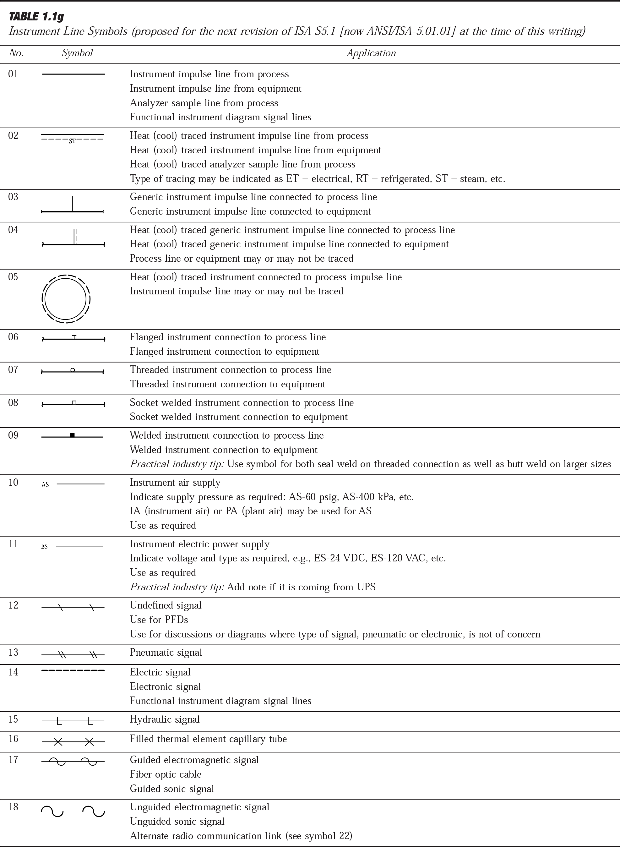
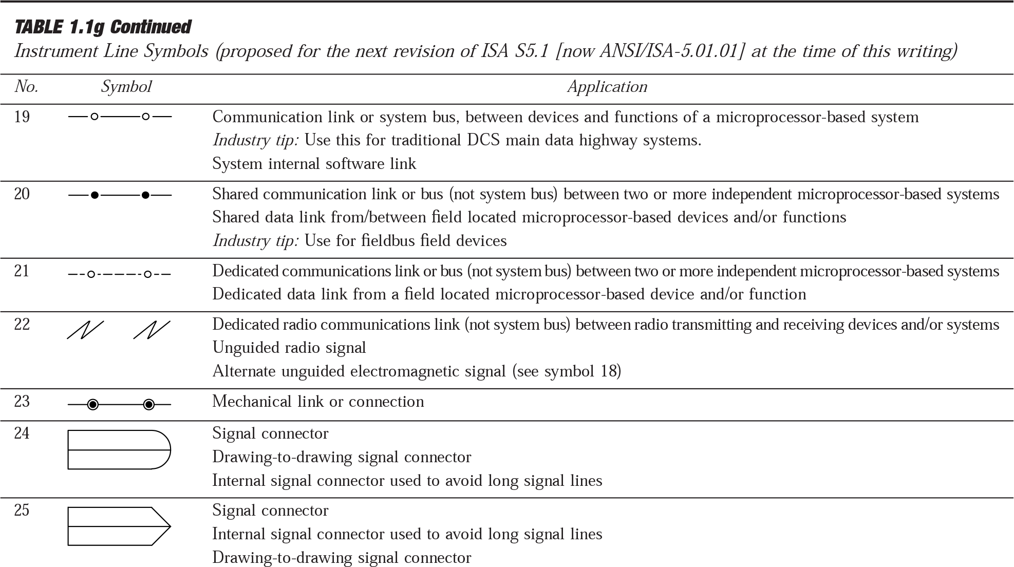
Table 1.1g, Instrument Line Symbols, contains lines used to represent process connections and the measurement and control signals that connect instruments and functions to the process and to each other.
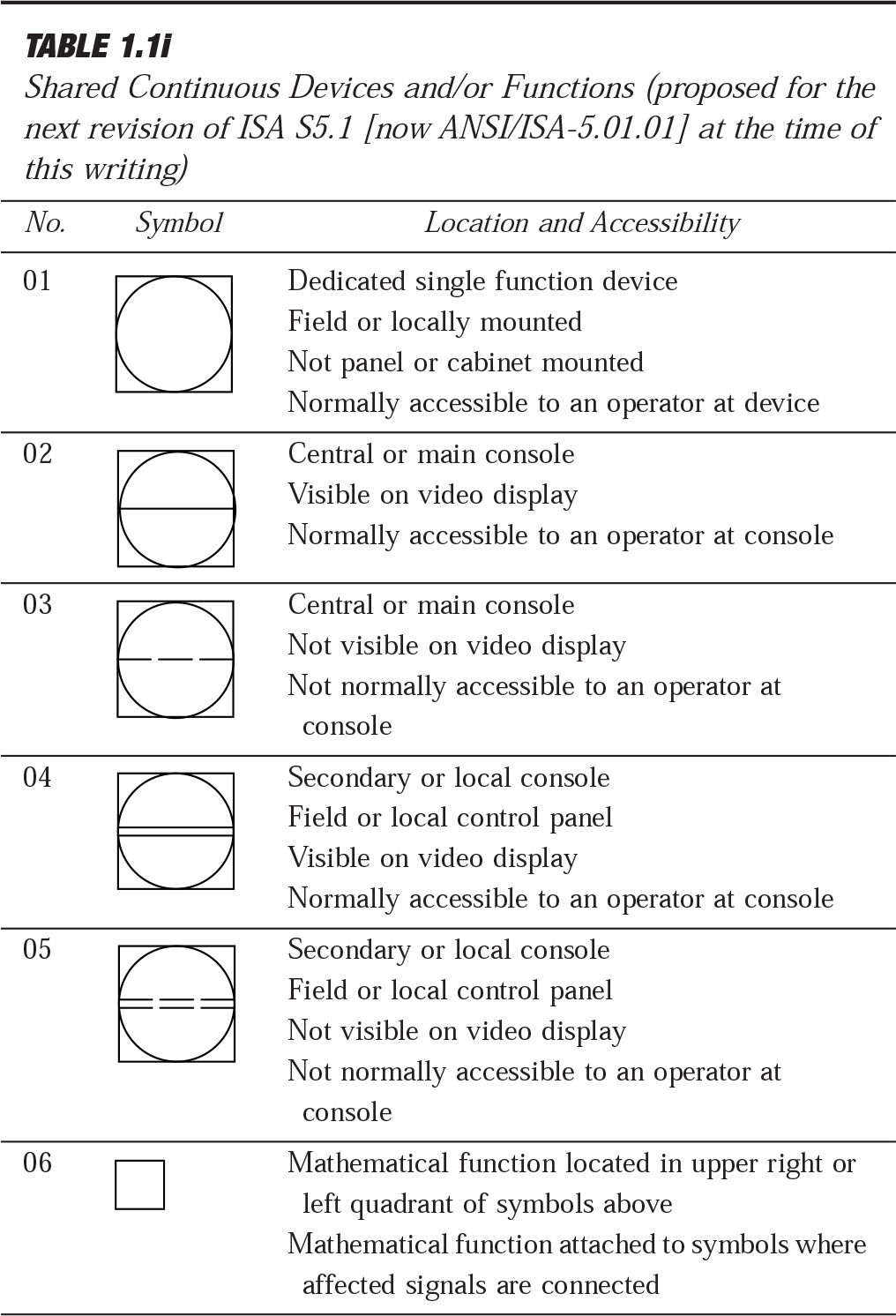
Tables 1.1h through 1.1k depict circles, squares, diamonds, hexagons, and lines used to represent the majority of hardware and software instruments and functions as follows:
Table 1.1h, Discrete (Individual) Devices and/or Functions, represents discrete hardware instruments and/or functions that are implemented in nonmicroprocessor-based systems similar or equal to single-case transmitters, controllers, indicators, or
recorders.
Table 1.1i, Shared Continuous Devices and/or Functions, represents shared and/or distributed software analog instruments and/or functions that are implemented in microprocessor-based systems similar or equal to distributed control or programmable logic control systems.
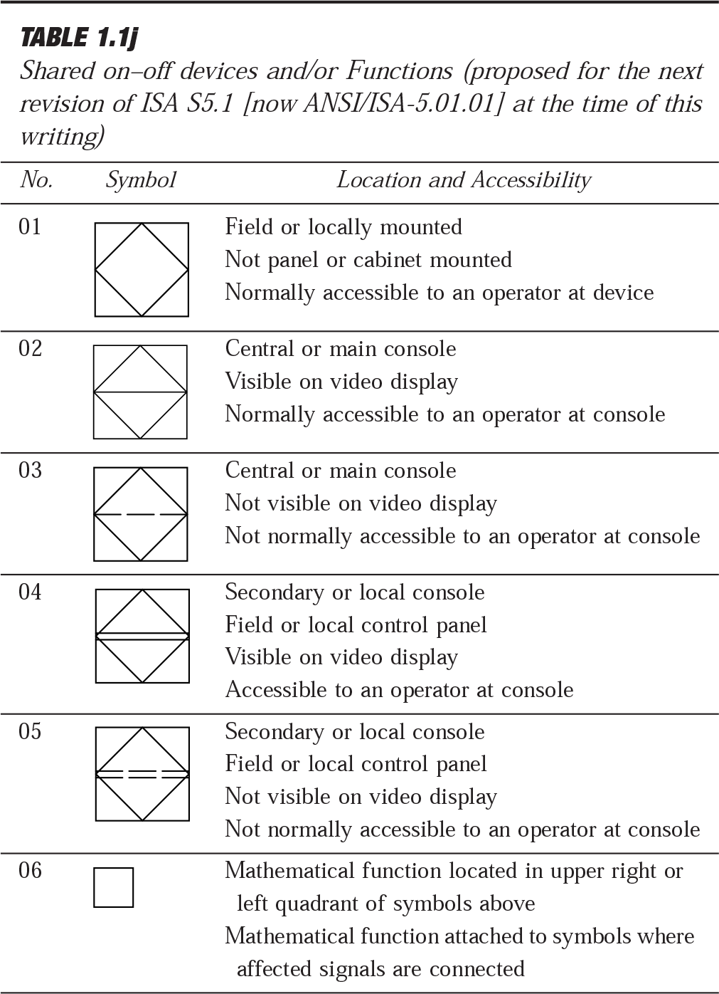
Table 1.1j, Shared On–Off Devices and/or Functions, represents shared and/or distributed on–off software instruments and/or functions that are implemented in microprocessor-based control systems similar or equal to a distributed control or programmable logic control systems.
Table 1.1k, Computer Devices and/or Functions, represents shared and/or distributed on–off software instruments and/or functions that are implemented in a computer-based control system.
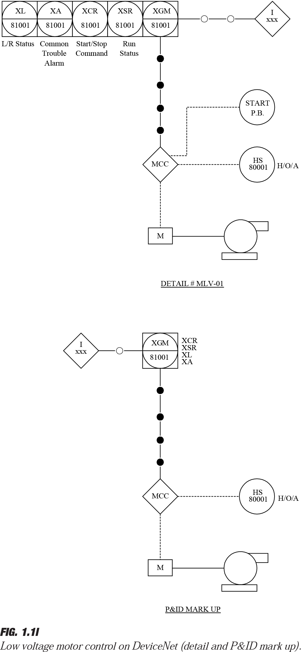
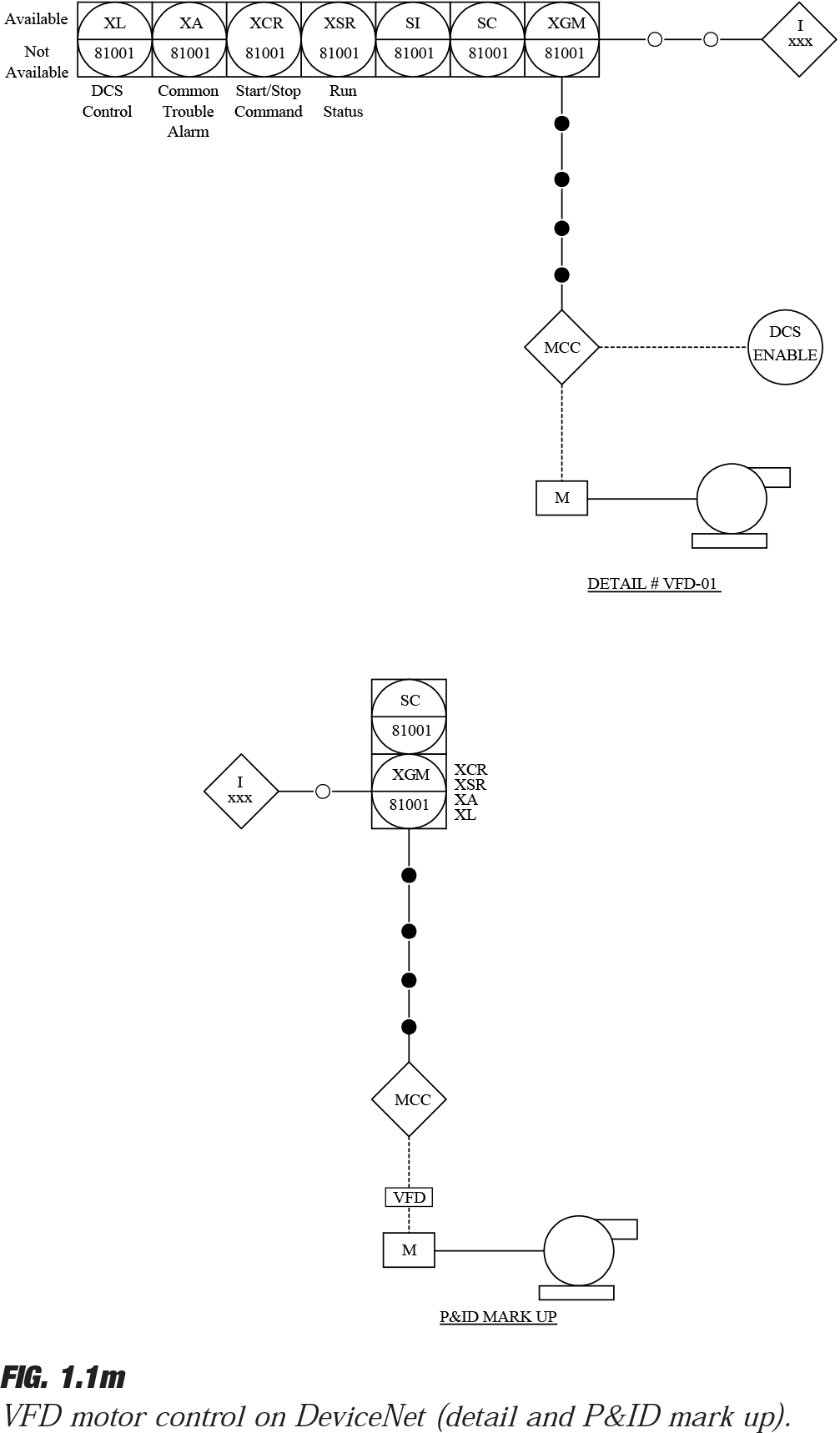
Figures 1.1l and 1.1m illustrate some practical but not standardized P&ID symbology for a fieldbus system (DeviceNet).
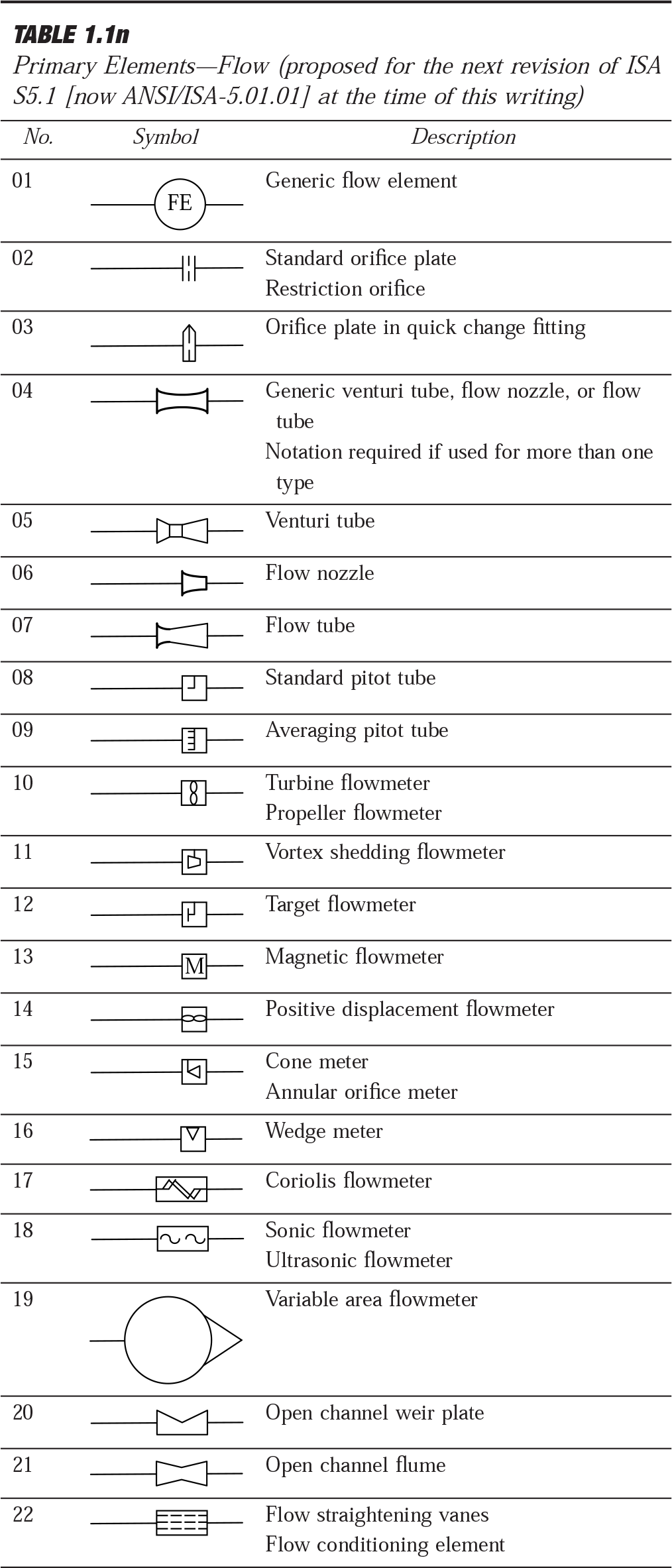
Table 1.1n, Primary Elements—Flow, describes various geometric shapes that represent primary measurement elements, such as orifice plates and thermocouples, that are located in the process piping.
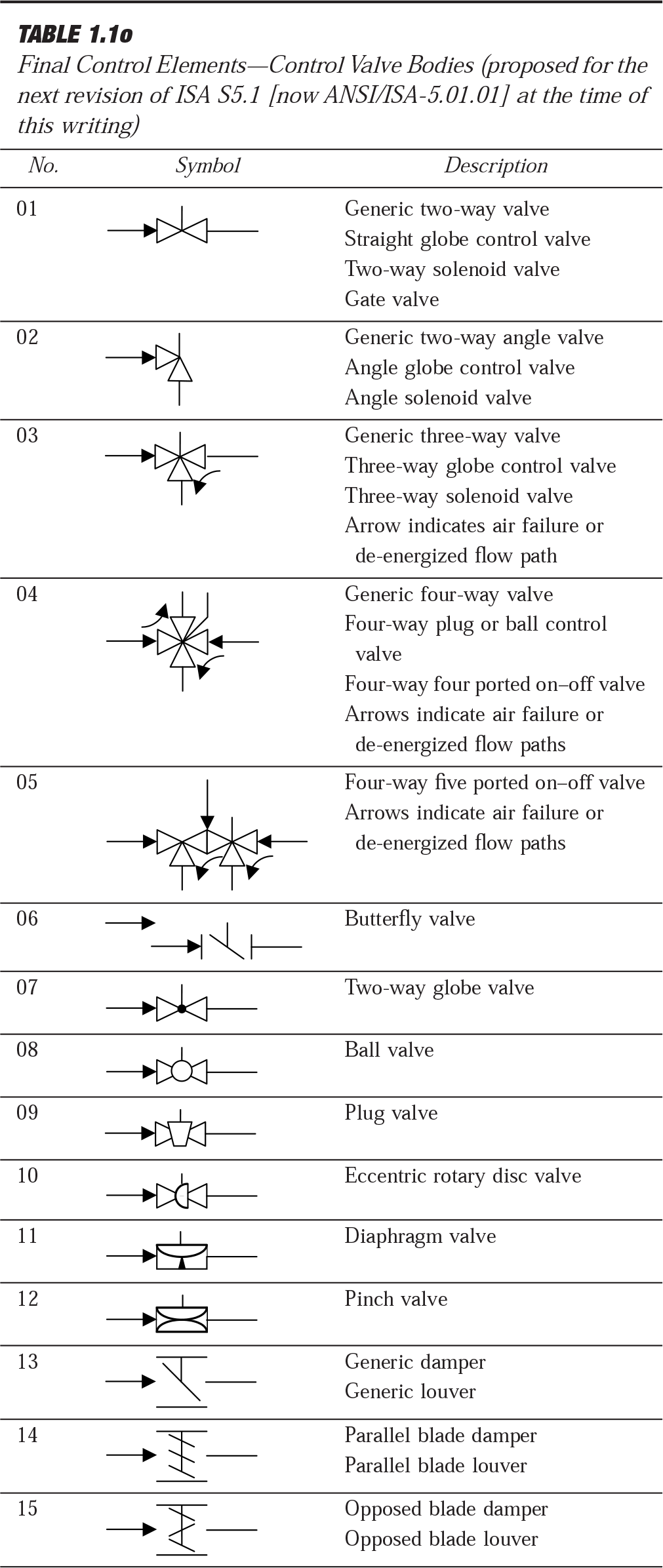
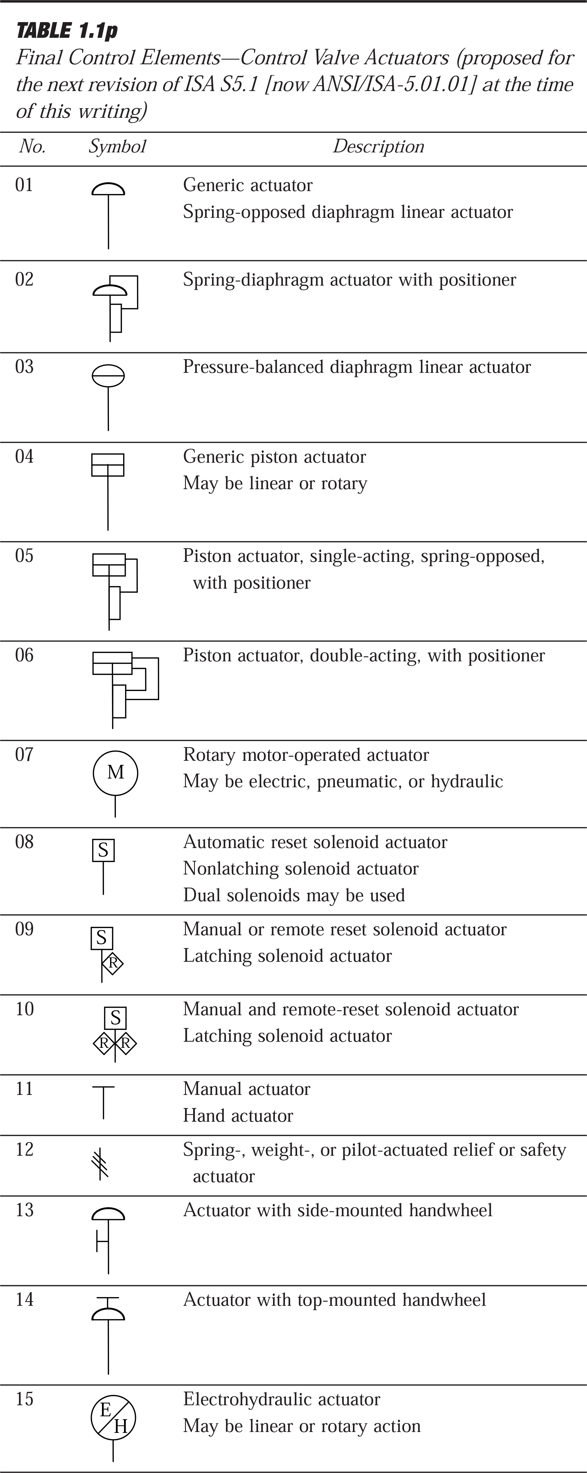
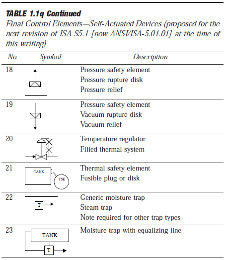
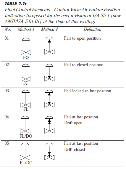
Tables 1.1o through 1.1r, Final Control Elements, consist of various geometric shapes that represent final control elements, such as control valves and their actuators, that are located in the process piping:
Table 1.1o–Control Valve Bodies
Table 1.1p–Control Valve Actuators
Table 1.1q–Self-Actuated Devices (includes such selfactuated elements as pressure control valves and pressure relief valves)
Table 1.1r–Failure Position Indicators for Control Valves (indicates the position which the valve takes when/if the actuating power fails)
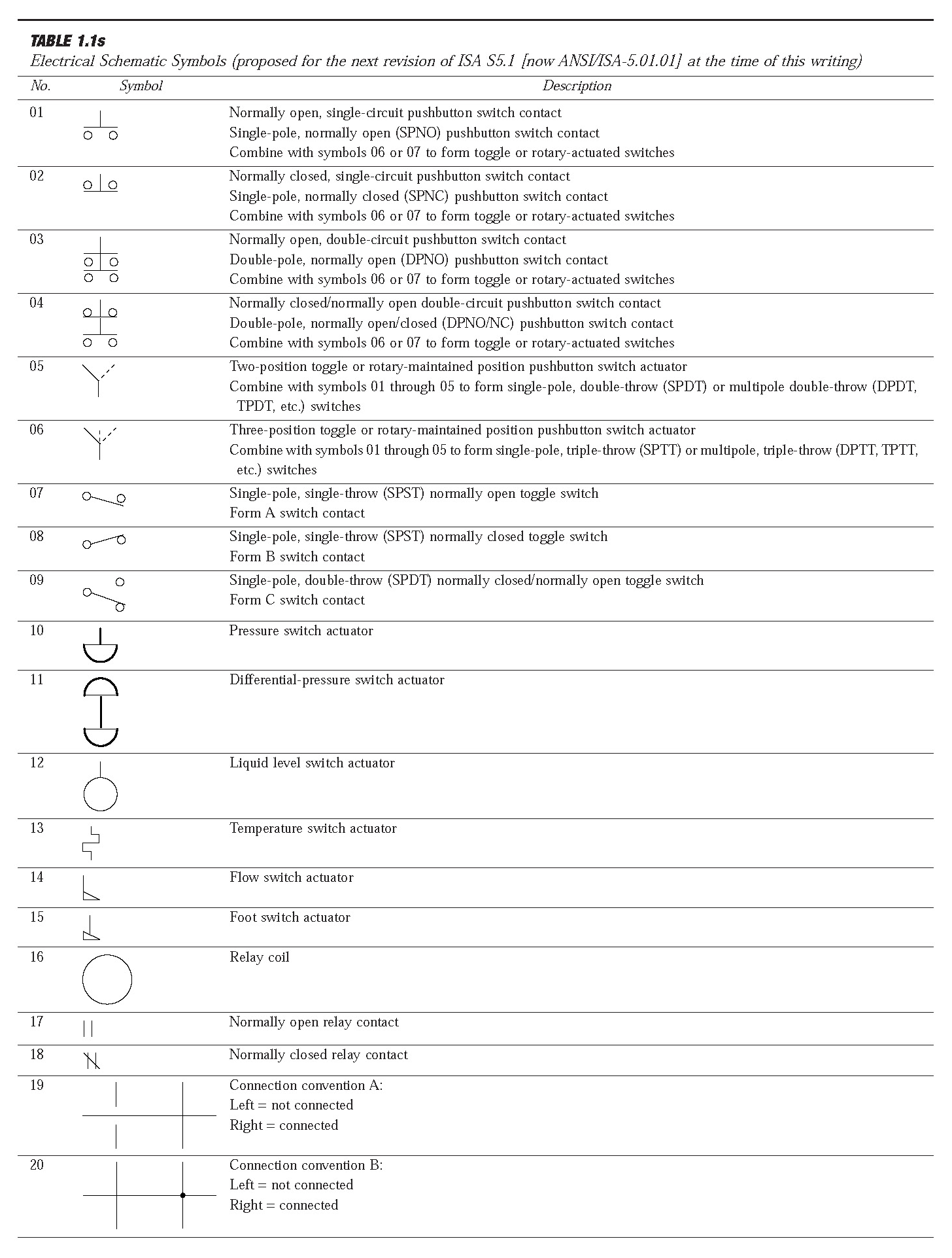
Table 1.1s, Electrical Schematic Symbols, represents electrical circuit elements.
Specific industrial application examples of the graphic symbol system will be found in a future series of S5.1 (now ANSI/ISA-5.01.01) Technical Reports. Sketches that are not all inclusive of acceptable methods of depicting instrumentation are included in the following text to illustrate the intent of the standard. However, the individual symbols and their meanings are to be mandatory in the future, imminent standard.
Guideline Modifications
These guidelines may be modified to suit the requirements of existing user-designed graphic symbols that are not included in this standard. When modified symbols are
adopted, they shall be fully described and detailed in the user/owner’s engineering or design standards.
Instrument Line Symbols
In Table 1.1g, symbols represent the following:
a) Instrument and device connections at process measurement points
b) Connections to instrument power supplies
c) Signals between measurement and control instruments and functions
Lines shall be
a) Fine in relation to process equipment and piping lines
b) As short as possible and consistent with clarity
Measurement and Control Devices and/or Function Symbols
See Table 1.1h, Discrete (Individual) Devices and/or Functions, in which symbols represent discrete devices that perform continuous and/or on–off functions that do not share control or display functions for the following:
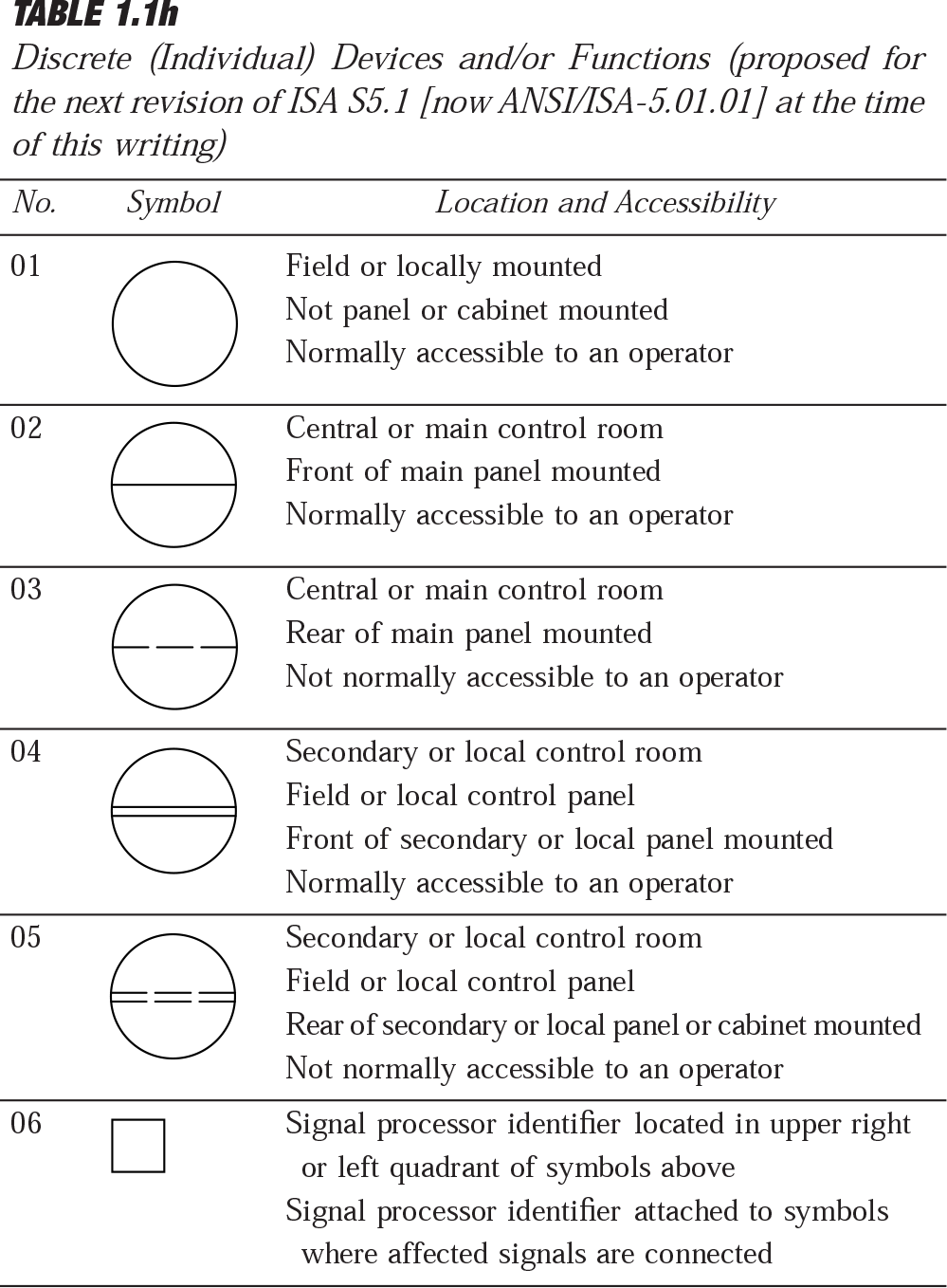
a) Measurement (transmitters, primary elements)
b) Indication (indicators, annunciators)
c) Control (controllers, control valves, switches, solenoids)
Limited operator accessibility (setpoint changes, control mode transfers, etc.) and unlimited engineer or technician accessibility through location and enclosure methods are shown.
Table 1.1i covers analog, digital, and/or discrete shared control devices and/or functions for continuous control, indication, calculation, and so forth that are microprocessor based and configurable. They communicate with each other and
share control or display functions in applications such as distributed control and programmable logic systems.
Limited operator accessibility (setpoint changes, control mode transfers, and so forth) and unlimited engineer accessibility is through local or wide area communications networks, keyboards, and video displays as shown.
Table 1.1j deals with analog, digital, and discrete control devices and functions for on–off or binary control, indication, calculation, and so forth that are microprocessor based and configurable. They communicate with each other and share control or display in distributed control and programmable logic systems.
Limited operator accessibility (setpoint changes, control mode transfers, and so on) and unlimited engineer accessibility is through local or wide area communications networks, keyboards, and video displays as shown.
The devices and functions in Table 1.1k include process plant computer-implemented regulatory and/or advanced control analog/digital/discrete (individual) control and indication functions that are mainframe computer or minicomputer based.
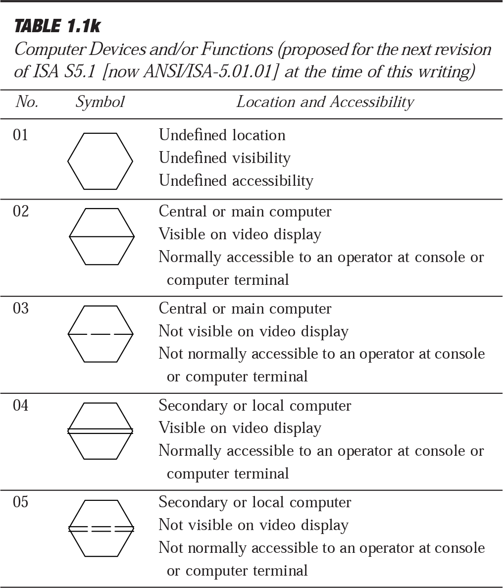
Limited operator accessibility (setpoint changes, control mode transfers, etc.), and unlimited engineer accessibility is through local or wide area communications networks, keyboards, and video displays as shown.
Fieldbus P&ID Examples: DeviceNet Figures 1.1l and 1.1m show the practical methods used by one EPCM company in establishing a P&ID detail and markup for a low-voltage
motor control plus a VFD motor control implemented with DeviceNet as the fieldbus. It should be pointed out that these figures do not completely conform to the ISA S5.1 (now ANSI/ISA-5.01.01) proposed standard and are a compromise born of necessity.
In Table 1.1n, symbols are pictorial representations of primary flow elements that generate a measurement or signal equal to, or a signal proportional to, a fluid flow rate or total flow.
In Table 1.1o, valve body symbols, when combined with valve actuator symbols, shall be used to represent control valves and solenoid valves as follows:
Symbols 01 through 05 may be used as generic symbols to represent control and solenoid valve bodies.
The remaining symbols may be used when it is desired to more clearly indicate a specific valve body type.
In Table 1.1s, contacts shall be shown in shelf condition.
Rising switch actuator will cause contacts to switch.
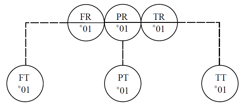
Multipoint, Multifunction, and Multivariable Devices and Loops
Multipoint devices are indicators or recorders that may be single or multivariable and receive input signals from two or more primary elements or transmitters.
Multivariable devices are indicators, recorders, and controllers that receive input signals from two or more primary elements or transmitters and control one manipulated variable.
Multifunction devices are controllers or switches that receive input signals from two or more primary elements or transmitters and control two or more manipulated variables.
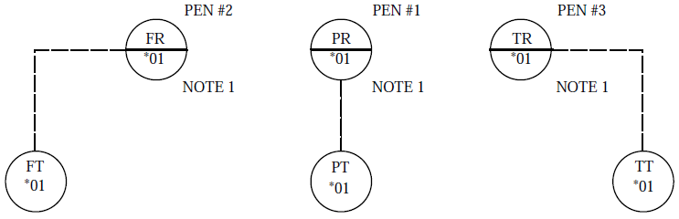
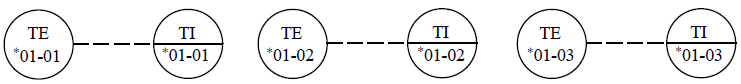
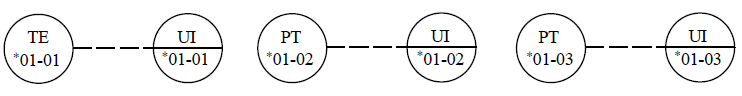
Single variable or multivariable multipoint indicators and recorders for two or three points shall be drawn with bubbles either
a) Tangent to each other in the same order, left to right, as the pen or pointer assignments:
b) Separate from each other, with pen or pointer number indicated preferably in upper right or left quadrant and a note defining instrument or device indicated in preferably
lower right or left quadrant:
Multipoint indicators and recorders for four or more points may be drawn with bubbles separate from each other, with point number indicated by adding a suffix to the tag numbers as follows:
a) Single variable:
b) Multivariable:
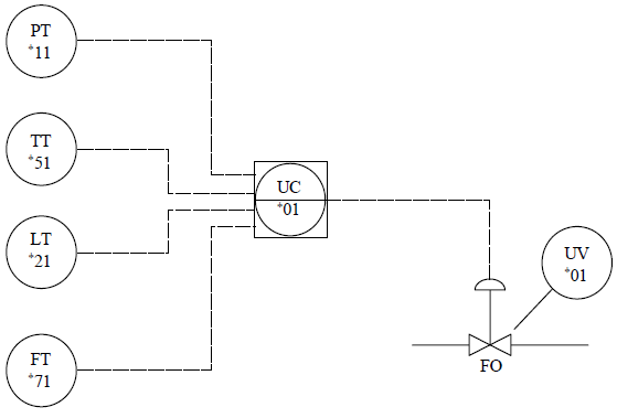
Multivariable controllers may be drawn with bubbles for each measured variable input and for the output to the final control element; measured variable indicators may be:
a) Shown:
b) Assumed:
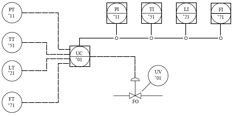
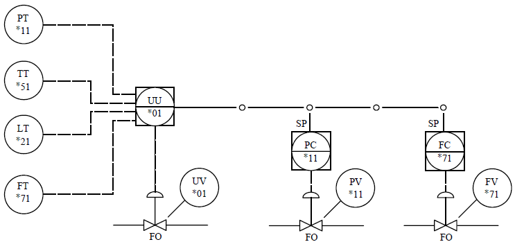
Multifunction controllers shall be drawn with bubbles for each measured variable input and output to final control elements; measured variable indicators may be:
a) Shown:
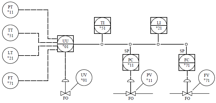
b) Assumed:
Fieldbus Devices, Loops, and Networks
Comments and Exceptions (Including Non-ISA Industrial
Practice) Instrument and control systems staff working at engineering, procurement, and construction management (EPCM) companies had to improvise on P&ID symbols for fieldbus devices, loops, segments, and networks throughout thelate 1990s and early 2000s. This has been the case while waiting for the draft standard work outlined in this section to be discussed and approved as the latest revision to ISA S5.1 (now ANSI/ISA-5.01.01). (For specific details on fieldbus technologies, please refer to later chapters and sections in this volume.)
Certain techniques and shortcuts used by several EPCM companies, and how they have handled fieldbus symbology, will be mentioned in this subsection. A few companies have generated their P&IDs using the proposed Instrument Line Symbol no. 20 (Table 1.1g) as the shared data links or FOUNDATION ™fieldbus (FF) segments between field located microprocessor- based devices as well as FF host systems. In this way, it is implicit that the devices connected by that symbol are fieldbus devices and do not need any further symbology or identification on the P&IDs. This symbol also has been used for other fieldbuses such as PROFIBUS PA, PROFIBUS DP, AS-i Bus, and DeviceNet (see Figures 1.1l and 1.1m).
Another symbol used by the EPCM companies for fieldbus has been the Instrument Line Symbol no. 19 (Table 1.1g), which is the current existing symbol (ANSI/ISA S5.1-1984[1992]) and normally the one used for data links and DCS data highways. This has been done occasionally when the EPCM company’s client/owner had specific, custom
P&ID symbology standards and was reluctant to change a worldwide standard to a new symbol such as no. 20. Once again, any field devices such as transmitters and control
valves that are connected together by Symbol no. 19 are now known to be fieldbus-type devices. The disadvantage is that the P&IDs must be studied carefully to determine real communication link, DCS data highway, system bus, or internal software link applications from the fieldbus applications.
Another EPCM company used the conventional analog electronic signal (Symbol no. 14 in Table 1.1g) at the urging of its client but added the suffix “FB” to each fieldbus device
bubble on the P&IDs. Once again, this was not a standardized approach, and it led to ambiguity and misunderstanding.
It is highly recommended that the proposed draft revision Instrument Line Symbol no. 20 (which we hope will be approved by the time this volume is released) be used for all types of fieldbus segments and networks.
P&IDs: Practical Aspects and Practices in the EPC Industry
Piping and instrument diagrams (P&IDs) are the basic documents describing a plant from mechanical and control point of view. They are sometimes called mechanical flow diagrams (MFDs) by some EPC and operating companies. Process flowsheets/diagrams (PFDs) are used and generated by process design engineering in the very early stage of the frontend engineering phase and do not normally include ISA symbols except in the most elementary fashion. However, they are the starting point for P&ID development.
The P&ID life cycle extends through the feasibility study, project estimate, detailed engineering phase, constructionphase, precommissioning, commissioning, and, finally, to exploitation of the plant. According to which phase the project is in, the P&IDs show different level of details to suit various needs.
1) During the feasibility study, not all equipment and lines are shown; only the major ones appear, such as used to follow the path of authorizations, obtain of financing, and so on. At this stage, only major equipment is sized, such as to show environmental impact, and effluent systems are studied to comply with the information requested by various environmental authorities. Only major lines are shown, without sizing information. Very few instruments and control loops are shown, and then only in the most simplified manner.
2) During the project estimate, all equipment is shown, but without auxiliary services such as cooling water to machinery. The lines are sized, and their material and rating are shown. All control loops are shown, or at least all transmitters, local instruments, and control valves. All motor-operated valves and safety valves are shown and are sized if possible. Small-bore/diameter piping (<2 in) is not shown unless it is made of an exotic material.
3) Within the detailed engineering phase, the P&IDs are issued several times, incorporating information as it becomes available from vendors or as derived from calculations and finalization of choices. Normally, there are about three or four issues before the issue for construction. At that time, the P&IDs shall show all equipment and all lines including services to machinery, drains, and vents (as far as piping is concerned) and all instruments, control loops, and valves (as far as instrumentation is concerned).
Each line shall be sized, classified, and numbered, meaning that each line is identified with nominal diameter, piping class (which defines the material), rating (unless the piping class covers only one rating), corrosion allowance, and winterization.
The control valves shall be shown with their true nominal diameter and flange rating along with block and bypass valves, handwheel, action on air failure, and possibly the pressure drop. If the valve is the angle type, the inlet and outlet shall be shown correctly. The transmitters shall be shown singularly, duplicated, or triplicated, with their pressure taps. If level bridles are used, they shall be shown with correct valving. The flow measurements shall show the correct type of primary element. Magnetic flowmeters that are required to run full should show the indication “low point.”
If some devices (such as desuperheaters) require special precautions, such precautions shall be shown to prevent wrong piping design (e.g., minimum unobstructed straight length = X feet). The safety valves shall be shown with size and rating of input and output connections plus the set pressure.
All vents, drains, silencers, and so on shall be shown.
If many vents use common silencers, this shall be clearly indicated by means of drafting or notes. The control loops shall be shown in complete form. However, in the power industry, some boiler manufacturers show the transmitters (since they are supplied by them) and the control loops in several different documents (vendor package drawings) to be delivered to the DCS supplier or the EPC company responsible for DCS design. To prevent multiple repeats of the same information, some typical sketches should be prepared covering, for instance, the indications and commands related to an on–off motor-operated valve, an inching motoroperated valve, high-voltage motors, low-voltage motors, on–off pneumatic valves, and so forth. The typical sketches shall be numbered and referred to nearby each device on the P&ID to which it applies.
Although the P&ID symbols are normally in accordance with ISA standards, it is recommended that a P&ID symbol key sheet be prepared with a summary of all equipment and instrument symbols used to prevent any misunderstanding.
The reader is referred to the previous subsection, “Inclusion of the New S5.1 Standard (now ANSI/ISA-5.01.01) in User/Owner Documents.”
The tag numbering of the instruments shall be in accordance with ISA guidelines, standards, and recommended practices previously covered in this section, and all components of a loop shall have the same distinctive number so as to simplify maintenance and understanding of the process.
In the case in which an instrument or loop is cancelled, its tag number shall not be used again to prevent the possibility of keeping the old process data that is no longer correct. The tag/loop cancellations must be carefully noted and retained in the instrument index, and especially in the computerized instrument database (IDB) that generates the index. For the same reason, if an instrument or a loop is moved to a different tapping point, it should be renamed—although this depends on different company standards/policies on this subject. In some cases, two pieces of equipment are used (e.g., two pumps, one spare to the other), which are named with the suffix A/B. Their relevant instruments are often tagged with the tag number suffixed with A/B. To avoid misinterpretations when two or three instruments are used in a redundant/voting configuration, it is suggested to attach suffixes to them using the letters X, Y, and Z.
Even though the P&IDs are not representative of the layout of the plant, it is recommended that the equipment be shown as it is to appear; e.g., a horizontal vessel shall be shown as horizontal and not vertical, and a boiler feed water pump with intermediate MP draft should be shown with the nozzles in correct sequence. A distillation column with different sections should be represented not as a constant one but to be roughly representative of the true situation. It is noted that the P&IDs are to be suitable for a take-off of the valves, reducers, branches, and instruments, but not for the take-off of piping and elbows.
The P&IDs depicting utility distribution or fire detection/ fighting instead follow the plant plot plan and include some instruments as well.
It is important that all instruments appear on the P&ID and that none is overlooked. If some instruments are supplied as an integral part of a machine (e.g., resistance temperature detectors in electric motor windings and vibration probes in a compressor or turbine), it is advisable that the manufacturer’s P&ID be numbered with the same system as the project P&IDs, and always from the viewpoint of taking care of all signals that will be connected to a PLC or DCS. In fact, most EPC companies supply the proper compatible tags and loop numbers from the IDB to the vendor after the first vendor document/drawing review and subsequent return to the vendor.
During construction and precommissioning, the P&IDs are used to keep track of the installed piping and instruments.
At the precommissioning stage, they are used to verify that the plant has been built according to the P&IDs issued for construction. This is called the check against P&IDs. Any discrepancy found during this check shall be resolved and the plant modified or, if acceptable, the P&IDs shall be marked up to prepare the “as-built” issue.
During commissioning, some modifications could be necessary to overcome operational problems that could arise.
These modifications could involve additional drains and vents, control strategy changes, and so forth and need to be recorded on the P&IDs to be introduced in the “as-built” issue.
During the life cycle of the plant, the P&IDs can be modified because of different products required, different feedstock, or additional treatment systems. This is even more evident in batch processes that can be modified to obtain different products. Sometimes, it is a concern that the revamping or debottlenecking of the original plant could be so extensive that the original P&IDs need to be redrawn. In this case, it is possible that starting from existing P&IDs could cause the introduction of several errors because they have not been updated.
The P&IDs have also a commercial impact on a project in that a payment is tied to their first issue. In defining the commercial aspects, one should determine to what extent the
first issue of the P&IDs shall be complete so as to avoid conflicts between the owner and the supplier. A possible request could be as follows:
• All lines sized, classified, and numbered
• All instruments tagged
• All set values of safety valves shown
To go even farther, the size of control valves could be shown.
The P&IDs are the first step in ensuring the safety of maintenance personnel, which today is based on widely used outsourcing. For example, people should immediately be warned about the risks involved in the case of piping that has a high rating, is made with an exotic material, has high corrosion allowance, has a thick insulation, or belongs to a system with high set values for the safety valves.