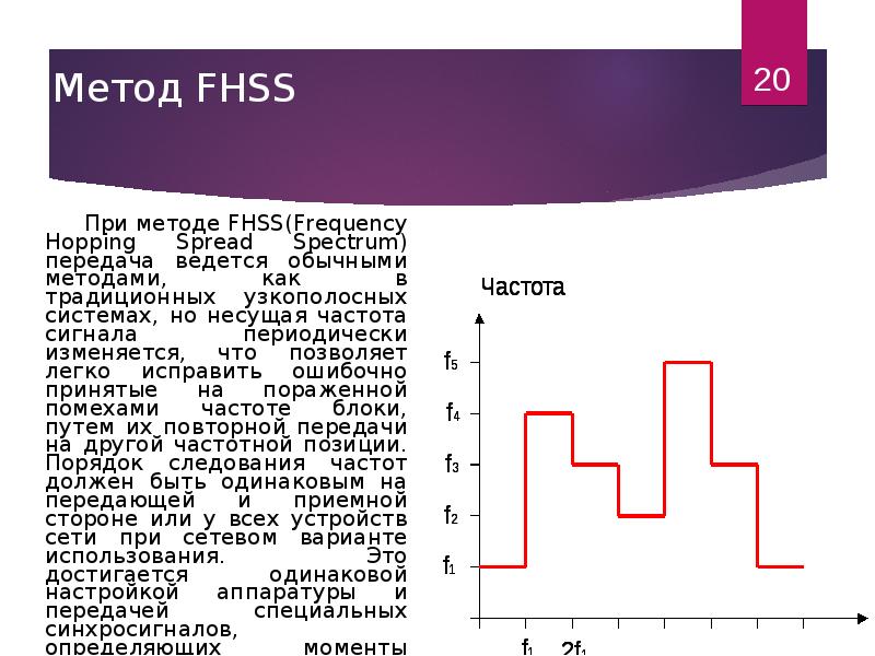
Frequency Spread Spectrum

🔞 ALL INFORMATION CLICK HERE 👈🏻👈🏻👈🏻
Frequency Spread Spectrum
Analog Devices Uses Cookies for Enhanced Online Performance
Technical Articles
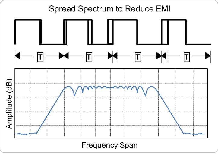
Spread Spectrum Frequency Modulation Reduces EMI
Some cookies are required for secure log-ins but others are optional for functional activities. Our data collection is used to improve our products and services. We recommend you accept our cookies to ensure you’re receiving the best performance and functionality our site can provide. For additional information you may view the cookie details . Read more about our privacy policy .
by
Kevin Scott and
Greg Zimmer
Download PDF
Electromagnetic Radiation (EMR), Electromagnetic Interference (EMI) and Electromagnetic Compliance (EMC) are terms that pertain to energy from electrically charged particles and the associated magnetic fields that can potentially interfere with circuit performance and signal transmissions. With the proliferation of wireless communications, the plethora of communication devices, and the growing number of communication methods (including cellular, WiFi, satellite, GPS, etc.) using more and more of the frequency spectrum (with some bands overlapping), electromagnetic interference is a fact of life. To mitigate the effects, many governmental agencies and regulatory organizations have set limits on the amount of radiation that can be emitted by communications devices, equipment and instruments. One example of such a specification, CISPR 16-1-3, deals with radio disturbance and immunity measuring apparatus and measuring methods.
Electromagnetic interference can be characterized as conducted (transmitted via the power supplies) or radiated (transmitted through the air). Switching power supplies generate both types. One technique Linear Technology has implemented to reduce conducted and radiated interference is Spread Spectrum Frequency Modulation (SSFM). This technique is used in several of our inductor and capacitor-based switching power supplies, silicon oscillators and LED drivers to spread the noise over a wider band, thereby reducing the peak and average noise at a particular frequency.
SSFM improves EMI by not allowing emitted energy to stay in any one receiver band for a significant length of time. The key determinants for effective SSFM are the amount of frequency spreading and the modulation rate. For switcher applications, spreading of ±10% is typical and the optimal modulation rate is dictated by the modulation profile. Various methods of frequency spreading are used for SSFM, such as modulating the clock frequency with a sine wave or a triangular wave.
Most switching regulators exhibit ripple that is frequency dependent; more ripple at lower switching frequencies and less at higher switching frequencies. As a result, a switcher’s ripple will exhibit an amplitude modulation if the switching clock is frequency modulated. If the clock’s modulating signal is periodic, such as a sine-wave or triangle-wave, there will be a periodic ripple modulation and a distinct spectral component at the modulating frequency (Figure 1).
Figure 1. Illustration of Switching Regulator Ripple Due to Sinusoidal Frequency Modulation of the Clock
Since the modulating frequency is much lower than the switcher’s clock, it may be difficult to filter out. This could lead to problems, such as audible tones or visible display artifacts, due to supply noise coupling or limited power supply rejection in the downstream circuitry. A pseudo-random frequency modulation can avoid this periodic ripple. With pseudo-random frequency modulation, the clock shifts from one frequency to another in a pseudo-random fashion. Since the switcher’s output ripple is amplitude modulated by a noise-like signal, the output looks as if there is no modulation and the downstream system implications are negligible.
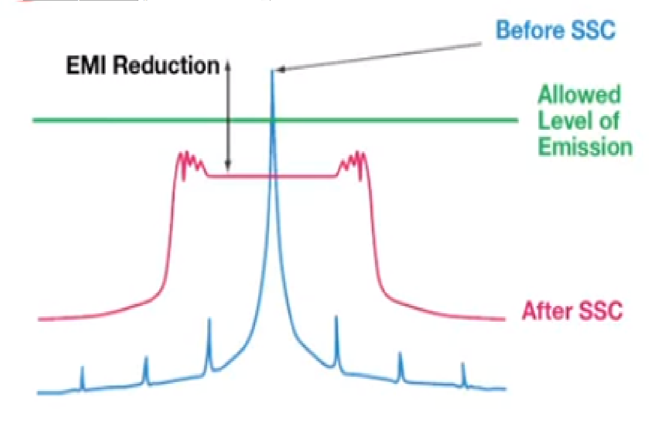
As the range of SSFM frequencies increases, the percentage of in-band time is reduced. In Figure 2 below, note how the modulated frequency appears as a wideband signal with a 20dB lower peak value when compared to the single unmodulated narrowband signal. If the emitting signal enters the receiver’s band infrequently and for short periods (relative to its response time), significant EMI reduction occurs. For example, frequency modulation of ±10% will be much more effective at EMI reduction than frequency modulation of ±2% 1 . However, switching regulators have a limited range of frequencies for which they can tolerate. As a general rule, most switching regulators can easily tolerate frequency variation of ±10%.
Figure 2. Spread Spectrum Modulation Results in a Wider Clock Frequency Band with Lower Peak Energy
Similar to the modulation amount, as the rate of frequency modulation increases (the hop-rate), the time that EMI will be “in-band” for a given receiver will decrease and EMI will be reduced. There is a limit, however, to the rate of frequency change (dF/dt) that a switcher can track. The solution is to find the highest modulation rate that does not impact the switcher’s output regulation.
The typical methods for measuring EMI are referred to as peak detection, quasi-peak detection or average detection. For these tests, the bandwidth of the test equipment is appropriately set to reflect the real world bandwidth of interest and determines the effectiveness of SSFM. When frequency modulated, the detector responds as the emissions sweep through the detector’s band. When the bandwidth of the detector is small compared to the modulation rate, the detector’s finite response time results in an attenuated EMI measurement. In contrast, the detector’s response time does not affect a fixed frequency emission and no EMI attenuation is observed. The peak detection test shows an improvement with SSFM that directly corresponds to the amount of attenuation. The quasi-peak detection test can show even further EMI improvement since it includes the impact of duty cycle. Specifically, a fixed frequency emission produces a duty cycle of 100%, while the duty cycle from SSFM is reduced according to the amount of time that the emissions are within the detector’s band. Finally, the average detection test can show the most dramatic EMI improvement since it filters the peak detected signal with a low pass, resulting in the average of in- band energy. Unlike fixed frequency emissions, where average and peak energy is equal, SSFM attenuates both the peak detected energy and the amount of in-band time, resulting in a lower average detection result. Many regulatory tests require that systems pass both quasi-peak and average detection tests.
At any instant in time, peak emissions from a switching regulator may appear to be the same, whether or not SSFM is enabled. How is the possible? The effectiveness of SSFM is in part dependent upon the bandwidth of the receiver. To receive an “instantaneous snapshot” of emissions requires an infinite bandwidth. Every practical system has a limited bandwidth. If the clock frequency changes faster than the bandwidth of the receiver, the reduction in received interference will be significant.
Figure 3. Switching Regulator Output Spectrum (9kHz Resolution Bandwidth) Using an LTC6908 with and without SSFM Enabled.
The LTC6909 , LTC6902 and LTC6908 are eight, four and two output, multiphase silicon oscillators with spread spectrum modulation. These devices are often used to clock switching power supplies. Multiphase operation effectively increases the systems switching frequency (since the phases appear as an increase in switching frequency) and spread spectrum modulation causes each device to switch over a range of frequencies, spreading the conducted EMI over a wider frequency band. The LTC6908 has a 5kHz to 10MHz frequency range, provides two outputs, and is available in two versions; the LTC6908-1 has two outputs with 180° phase-shift between them and the LTC6908-2 has two outputs with a 90° phase shift between them. The former is ideal for synchronizing two single switching regulators and the latter is ideal for synchronizing two dual, 2-phase switching regulators. The quad LTC6902 has a 5kHz to 20MHz freqeuncy range and can be programmed for 2-, 3- or 4-phases that are equally spaced. The LTC6909 features a 12kHz to 6.67MHz frequency range and can be programmed for up to 8 phases.
To address the periodic ripple mentioned above, these silicon oscillators use a pseudo-random frequency modulation. Using this technique, the switching regulator clock is shifted from one frequency to another in a pseudo-random fashion 2 . The higher the rate of frequency shifting, or the hop-rate, the less time the switcher is operating at a given frequency and the less time EMI will be “in-band” for a given receiver interval.
There is a limit, however, to the rate of frequency hopping. If the frequency hops at a rate beyond the switching regulator’s bandwidth, output spikes may occur at the clock frequency transition edge. Lower switcher bandwidths result in more pronounced spikes. For this reason, the LTC6908 and LTC6909 include a proprietary tracking filter that smooths the transition from one frequency to the next (the LTC6902 uses an internal 25kHz lowpass filter). The internal filter tracks the hop rate to provide optimal smoothing for all frequencies and modulation rates.
Figure 4. Pseudo-Random Modulation Illustrating the Effect of the LTC6908/LTC6909 Internal Tracking Filter
This filtered modulating signal may be acceptable for many logic systems but the cycle-to-cycle jitter issues must be considered carefully. Even with the tracking filter, the bandwidth of a given regulator may still be insufficient for high rates of frequency modulation. For bandwidth limitations, the LTC6908/LTC6909 frequency hop rate can be reduced from a default rate that is 1/16th of the nominal frequency, to a rate of 1/32nd or 1/64th of the nominal frequency.
Switching regulators operate on a cycle-by-cycle basis to transfer power to the output. In most cases, the frequency of operation is either fixed or is a constant based on the output load. This method of conversion creates large components of noise at the frequency of operation (fundamental) and multiples of the operating frequency (harmonics).
LTM4608A 8A, 2.7V to 5.5V IN DC/DC µModule Buck Regulator with SSFM
To reduce switching noise, the LTM4608A can operate with spread spectrum enabled by tying the CLKIN pin to SV IN (low power circuitry supply voltage pin). In spread spectrum mode, the LTM4608A’s internal oscillator is designed to produce a clock pulse whose period is random on a cycle-by-cycle basis but fixed between 70% and 130% of the nominal frequency. This has the benefit of spreading the switching noise over a range of frequencies, thus significantly reducing the peak noise. Spread spectrum operation is disabled if CLKIN is tied to ground or if it’s driven by an external frequency synchronization signal. Figure 5 shows the operating circuit with spread spectrum operation enabled. A capacitor value of 0.01µF must be placed from the PLLLPF pin to ground to control the slew rate of the spread spectrum frequency change. Component values are determined from the equation R SR ≥ 1 / −(ln(1− 0.592/V IN )*500*C SR ).
Figure 5. LTM4608A with Spread Spectrum Enabled
LT8609 42V Input, 2A Synchronous Buck Converter with SSFM
The LT8609 is a micropower, step-down converter that maintains high efficiency at high switching frequencies (93% at 2MHz), allowing smaller external components. SSFM mode operates similar to pulse skipping mode operation, with the key difference that the switching frequency is modulated up and down by a 3 kHz triangle wave. The modulation range is set at the low end by the switching frequency (which in turn is set by the resistor on the RT pin), and at the high by a value approximately 20% higher than the frequency set by RT. To enable spread spectrum mode, tie the SYNC pin to INTVCC or drive it to a voltage between 3.2V and 5V.
LTC3251 / LTC3252 Charge-Pump Step-Down Regulator with SSFM
The LTC3251 / LTC3252 are 2.7V to 5.5V, single 500mA/dual 250mA charge-pump-based step-down regulators that produce a clock pulse whose period is random on a cycle-by-cycle basis but fixed between 1MHz and 1.6MHz. Figures 6 and 7 show how the spread spectrum feature of the LTC3251 significantly reduces the peak harmonic noise and virtually eliminates harmonics compared to a conventional buck converter. Spread spectrum operation is selectable with the LTC3251 but is always enabled with the LTC3252.
Figure 6. LTC3251 with SSFM Disabled
Figure 7. LTC3251 with SSFM Enabled
LT3795 110V Multitopology LED Controller with SSFM
Switching regulator LED drivers can also be troublesome for automobiles and display lighting applications concerned with EMI. To improve EMI performance, the LT3795 110V multitopology LED driver controller includes SSFM. If there is a capacitor at the RAMP pin, a triangle wave sweeping between 1V and 2V is generated. This signal is then fed into the internal oscillator to modulate the switching frequency between 70% of the base frequency and the base frequency, which is set by the clock frequency setting resistor, RT. The modulation frequency is set by the equation 12µA/(2 • 1V • C RAMP ). Figures 8 and 9 show the noise spectrum comparison between the conventional boost switching converter circuit (RAMP pin tied to GND) and a spread spectrum modulation enabled boost switching converter (6.8nF at the RAMP pin). Figure 8 shows the average conducted EMI and Figure 9 shows peak conducted EMI. The results of EMI measurements are sensitive to the RAMP frequency selected with the capacitor. 1kHz is a good starting point to optimize peak measurements, but some fine tuning of this value may be necessary to get the best overall EMI results in a particular system.
Figure 8. LT3795 Average Conducted EMI
Figure 9. LT3795 Peak Conducted EMI
LT3952 Multitopology 42V IN , 60V/4A LED Driver with SSFM
The LT3952 is a 60V/4A power switch, constant current, constant voltage multitopology LED driver that features optional SSFM. The oscillator frequency is varied in a pseudo-random manner from the nominal frequency (f SW ) to 31% above nominal in 1% steps. This unidirectional adjustment allows the LT3952 to avoid a sensitive frequency band (such as the AM radio spectrum) in the system simply by programming the nominal frequency slightly above it. The proportional step size allows the user to easily determine the clock frequency value (RT pin) for his specified EMI test bin size, and the pseudo-random method provides tone suppression from the frequency variation itself.
The pseudo-random value is updated proportionally to the oscillator frequency, using a rate of f SW /32. This rate allows multiple passes of the entire group of frequencies during standard EMI test dwell times.
Figure 10. LT3952 Average Conducted EMI
Linear Technology has many other products that effectively use design techniques to reduce EMI. As mentioned, using SSFM is one technique. Other methods include slowing down fast internal clock edges and internal filtering. Another novel technique is accomplished with our Silent Switcher ™ technology, which uses the layout to effectively reduce EMI. The LT8640 is a unique 42V input, micropower, synchronous step-down switching regulator that combines Silent Switcher techniques and SSFM to reduce EMI. So the next time EMI is an issue in your design, be sure to look for our low EMI products that make it easier for you to be compliant to EMI standards.
1. ±2% SSFM is common for microprocessors and data clocks, because they cannot tolerate large frequency variation.
2. The repetition rate of the full pseudo-random sequence is guaranteed to be less than 20Hz.
Kevin Scott works as a Product Marketing Manager for the Power Products Group at Analog Devices, where he manages Boost, Buck-Boost and Isolated Converters, LED Drivers and Linear Regulators. He previously worked as a Senior Strategic Marketing Engineer, creating technical training content, training sales engineers and writing numerous website articles about the technical advantages of the company’s broad product offering. He has been in the semiconductor industry for 26 years in applications, business management and marketing roles.
Kevin graduated from Stanford University in 1987 with a BS in Electrical Engineering and started his engineering career after a brief stint in the NFL.
Greg Zimmer is the Marketing Manager for Analog Devices Battery Management Systems group, and has experience in product marketing across a broad range of high performance signal conditioning ICs. Greg’s background includes marketing, technical marketing, applications engineering and analog circuit design.
Greg received a BS degree in Electrical Engineering / Computer Science from the University of California, Berkeley and a BA degree in Economics from the University of California, Santa Cruz.
Multiphase Oscillator with Spread Spectrum Frequency Modulation
Resistor Set SOT-23 Oscillator with Spread Spectrum Modulation
Low V IN , 8A DC/DC μModule (Power Module) Regulator with Tracking,...
42V, 3A Synchronous Step-Down Regulator with 2.5µA Quiescent Current
Dual, Low Noise, Inductorless Step-Down DC/DC Converter
110V LED Controller with Spread Spectrum Frequency Modulation
1 to 8 Output, Multiphase Silicon Oscillator with Spread Spectrum Modulation
Interested in the latest news and articles about ADI products, design tools, training and events? Choose from one of our 12 newsletters that match your product area of interest, delivered monthly or quarterly to your inbox.
Spread spectrum - Wikipedia
Spread Spectrum Frequency Modulation Reduces EMI | Analog Devices
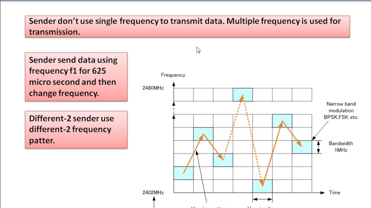
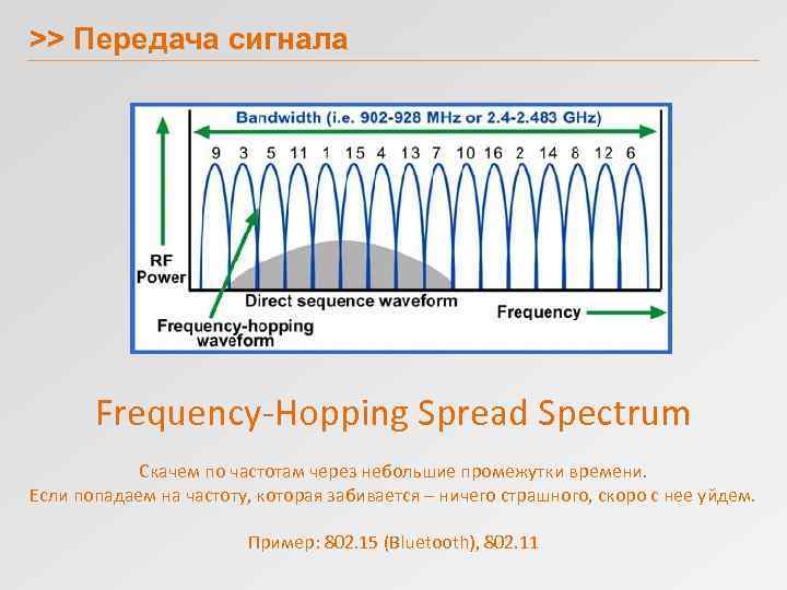
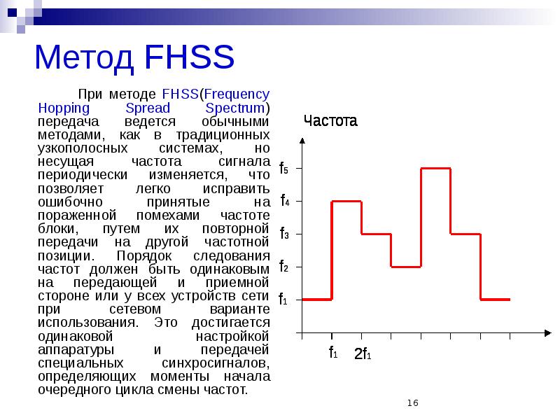
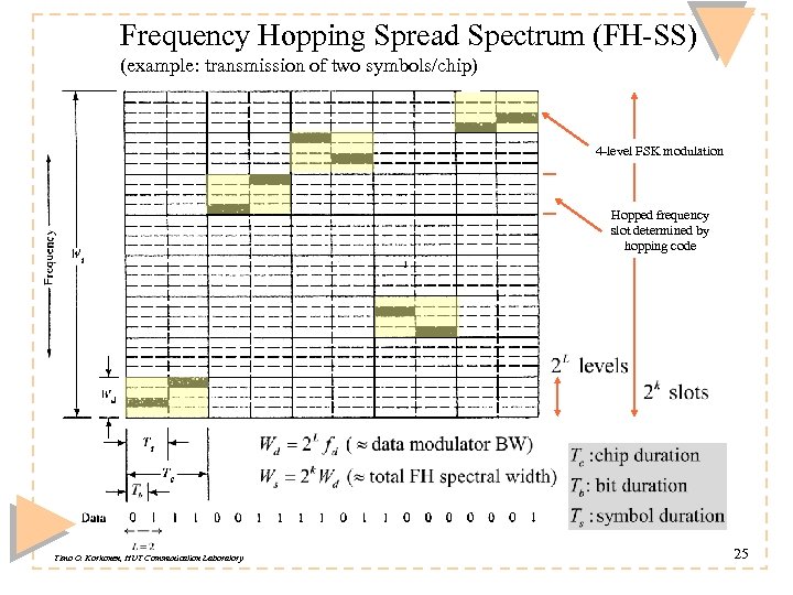
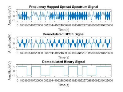
Frequency -Hopping Spread Spectrum (FHSS) The FHSS method does exactly...
Frequency Hopped Spread Spectrum (FHSS) - Tutorialspoint
Understanding Spread Spectrum for Communications - NI
Parametric Search
>
Power
>
Sensors
>
Analog
>
Interface
>
Communications
>
Embedded Security
>
Microcontrollers
>
iButton and Memory
>
Automotive
>
Military
>
All
Parametric Search
>
Power
>
Sensors
>
Analog
>
Interface
>
Communications
>
Embedded Security
>
Microcontrollers
>
iButton and Memory
>
Automotive
>
Military
>
All
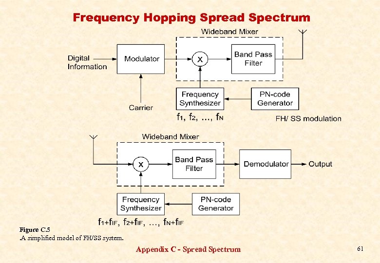
Abstract: This application note is a tutorial overview of spread-spectrum principles. The discussion covers both direct-sequence and fast-hopping methods. Theoretical equations are given to allow performance estimates. Relation to CDMA and TDMA is provided. A schematic of a code sequence generator is shown. Spectral plots illustrate direct-sequence spread-spectrum (DSSS) and frequency-hopping spread-spectrum (FHSS) methods.
C/B = (1/ln2) × ln(1 + S/N) = 1.443 × ln(1 + S/N)
C/B = 1.443 × (S/N - 1/2 × (S/N)² + 1/3 × (S/N)³ - ...)
Outdoor T1
Spy Public Sex
Mature Casting Porn
Topless Train Rides Porn
Naughty America 2021