Flipper Zero RGB backlight guide
ЖеняDisclaimer: do it on your own risk, neither Flipper devices, nor me are not responsible for any damage you can made to your Flipper or yourself with this modification.
Also please keep in mind that the power consumption of backlight will become higher.
So the procedure of enabling RGB backlight is following:
Go to the device passport, press ↓→→→◯◯, after this the color menu become available.

Just kidding. You need to install custom backlight PCB, c̶u̶t̶ ̶s̶o̶m̶e̶ ̶p̶l̶a̶s̶t̶i̶c̶ and install custom firmware.
So here the list of requirements:
- Screwdrivers ph1 and ph2
- Soldering iron with flux, tin and so on. If you can solder you should know
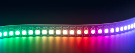
- At least 3 SK6805 1515 LEDs AliExpress AdaFruit Amazon
- Custom backlight PCB. You can order one in JLCPCB, PCBWay, or wherever you want, using this gerber files The PCB thickness should be 0,6mm, the rest of parameters might be left as is
- Few thin wires to make some connections
- 3 pcs of 0,1uF 0603 SMD capacitors
- Custom firmware with RGB backlight support. Here's actual repo with the binaries and code made by @Quen0n

I'm here not to teach you how to solder, but JFYI I used following method: as I was out of soldering paste I've just created solder pads on the backlight PCB with a regular soldering iron, put LEDs on them and heated the PCB from reverse side by hot air soldering station. If you don't have one you can use a regular iron or frying pan.
Then you need to disassemble your Flipper. You can check teardown guide on iFixit.
Next step is to remove the screen. You need to detach screen connector and unsolder two points of backlight pads
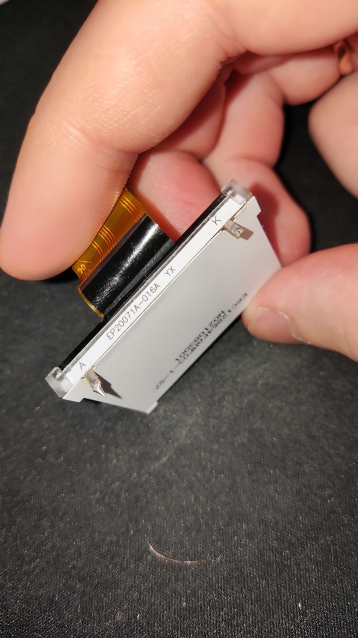
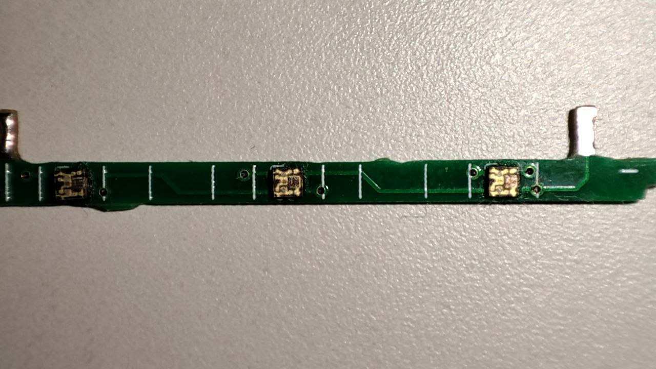
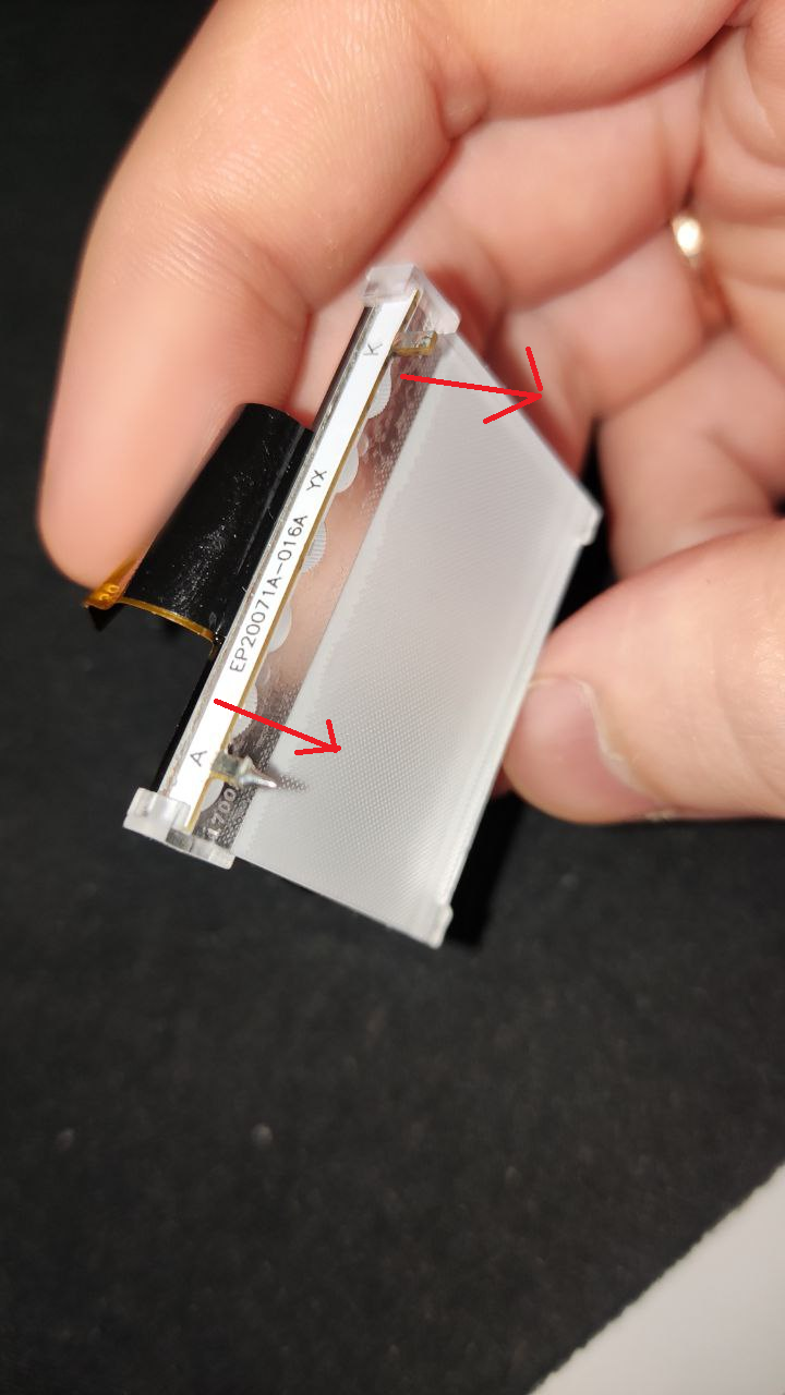
Remove white reflector from the screen backside and pull the original backlight PCB as shown:
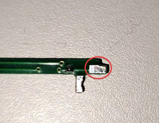
Solder a jumper wire to the control contact on the new PCB
T̶h̶e̶n̶ ̶y̶o̶u̶ ̶n̶e̶e̶d̶ ̶t̶o̶ ̶c̶u̶t̶ ̶t̶h̶e̶ ̶s̶c̶r̶e̶e̶n̶ ̶c̶h̶a̶s̶s̶i̶s̶ ̶a̶ ̶b̶i̶t̶ ̶a̶n̶d̶ ̶t̶h̶e̶ ̶e̶x̶t̶e̶r̶n̶a̶l̶ ̶b̶l̶a̶c̶k̶ ̶f̶r̶a̶m̶e̶
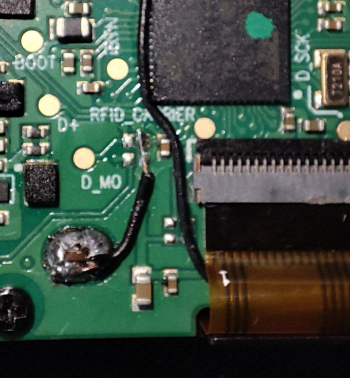
There's no need to cut the plastic parts, you can pass the control wire under the screen flat cable.
Assemble the screen back don't forget the white reflecting screen), put it back to Flipper and cover everything back with the black screen frame.
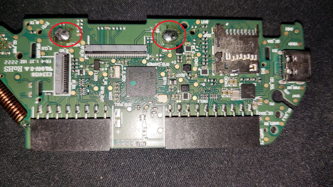
Now it's time to attach wires:
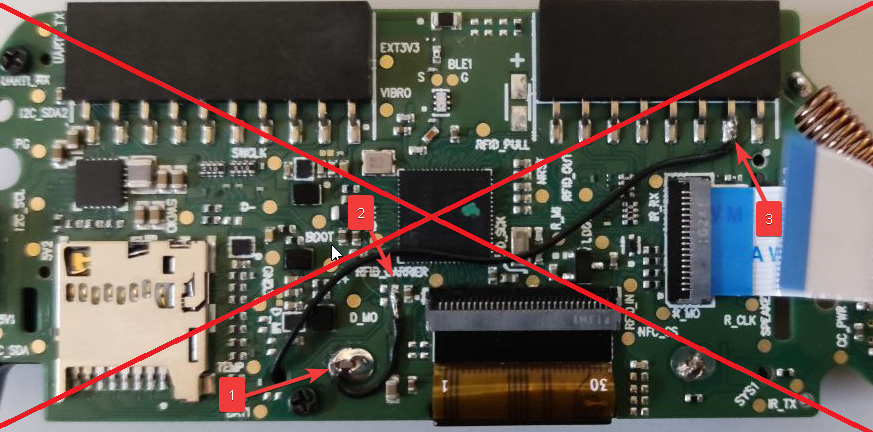
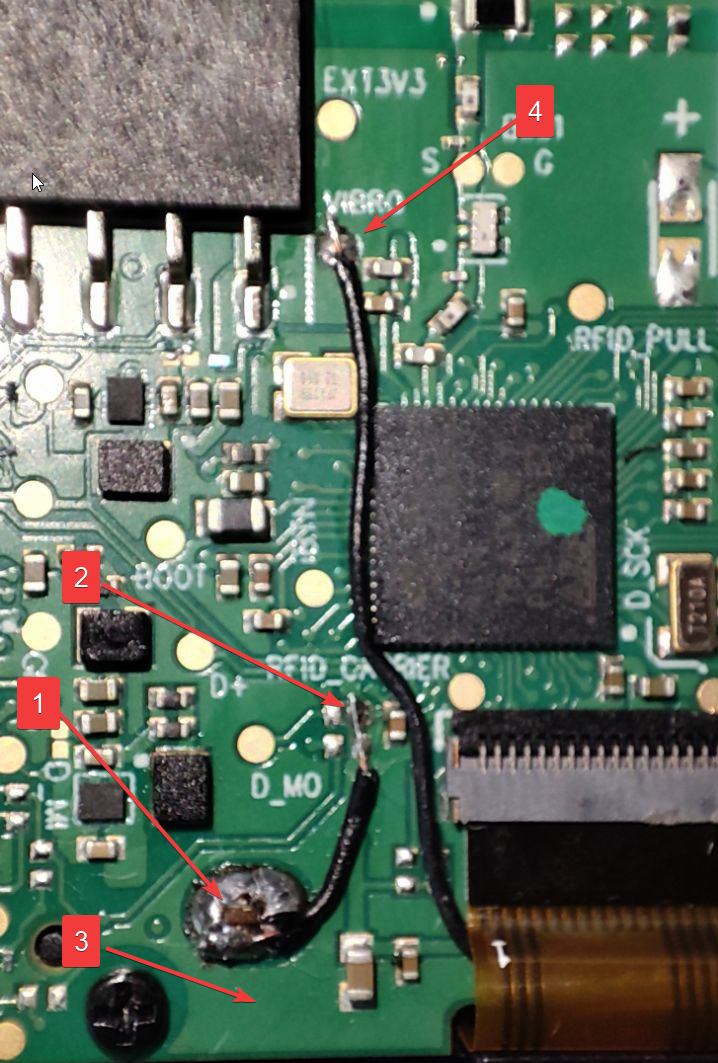
The benefit of using vibro line is that you don't need to sacrifice one of GPIO pins. Vibro and backlight can share the same line not interfering with each other
That's basically it, assemble everything back, flash the firmware and enjoy your g̶a̶y̶ gamer-backlight.
Questions/commentsisuggestons are welcomed in Flipper Telegram chat
You can find me there as @hitriy (please don't PM without a reason). The author of the firmware changes is @Quen0n (please don't PM and use public chat to contact as well)