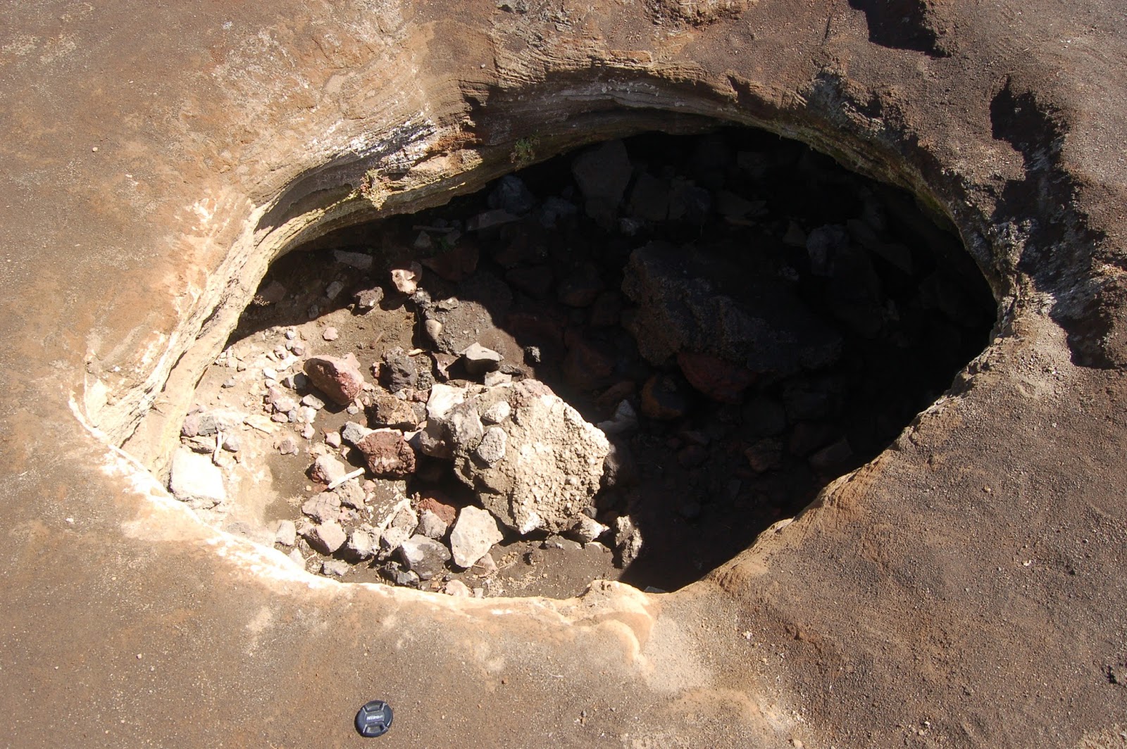
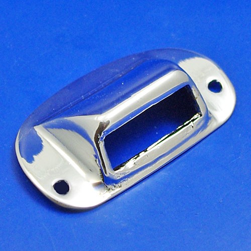
Drain Hole

🛑 👉🏻👉🏻👉🏻 INFORMATION AVAILABLE CLICK HERE👈🏻👈🏻👈🏻
Drain holes must be provided at the low point of the vent piping to prevent liquid or ice accumulation in the relief valve discharge.
Individual panel design features should include drain holes located at the lowest extremity of the section in subsequent parent subassemblies. Process related features must include protection by oils approved to give at least 3 months of protection in the press shop, storage and assembly. Panels must be burr-free to limit damage in transportation, prevent localized contact with bimetallic assemblies, and ensure paint depletion does not occur at panel edges (which can give premature rust bleeding at cut edges). It is emphasized that, in the case of bolt-on panels such as aluminum front wings, attachment directly to steel substructures, if unavoidable, should make use of galvanized nuts, bolts and washers, or efficient use of gasket materials to prevent longer term perforation resulting from bimetallic corrosion . Aluminum skins attached to steel inner structures should be separated by a uniformly applied layer of adhesive or appropriate sealer.
Inevitably, due to compromise with other design criteria, e.g. reinforcements within sections of front longitudinal panels to meet impact resistance – which may conflict with the size/number of electroprimer access holes or create contacting surfaces – paint coverage may be impaired. To counter such weaknesses, it is necessary to use supplementary protective systems comprising sprayed organic or polymer compounds. These are briefly described in the next section, following a more detailed description of the primary metallic, paint and pretreatment protection systems.
In single layer homogeneous reservoirs, the behavior of wells with multiple horizontal drain-holes follows a logic similar to partially open and multi-fractured horizontal wells, discussed in previous sections:
At early time, the different branches produce independently and, when the different drain-holes have the same skin, the behavior is equivalent to a single horizontal well with a total effective length defined as the sum of the lengths of all branches.
Later, the response deviates due to interference effects between the different horizontal sections. The flow geometry is a function of both horizontal and vertical distances between the branches, and orientation. An analytical simulator is required to properly interpret the well response.
Finally, pseudo radial flow towards the multilateral horizontal well can develop.
On Fig. 3.44 , two examples of multilateral horizontal well responses are compared to the horizontal well of similar total length. The drain-hole sections are perpendicular with two and four branches (L and + shape). At intermediate time, the interference effects produce an increase of the pressure response, and the derivative deviates above the half unit slope straight line of the single drain horizontal well curve. No mechanical skin damage is assumed on the three curves. The total skin S TH of the horizontal well is S TH =−6.8 whereas for the multilateral well examples S TH is respectively −6.6 and −6.2 with the L and + geometries.
Figure 3.44 . Multilateral horizontal well. Log-log scales, p D versus t D / C D . C D = 100, L = 1000ft (500+500 and 250+250+250+250), S wi = 0, h = 100ft, r w = 0.25ft, k V / k H = 0.1, z w / h = 0.5.
For a given total effective length, increasing the number of intersecting branches does not improve the productivity of horizontal wells in reservoirs with isotropic horizontal permeability ( Larsen, 1996a ; Salas et al., 1998 ). When the horizontal perforated segments do not intersect, Larsen shows that the total skin S TH can be expressed as a function of the dimensionless distance r D between the segments, with a decreasing function of ln r D . On the examples Fig. 3.45 where the distance between the two producing segments is large enough, the response becomes independent of the orientation of the branches and the total skin of the two multilateral horizontal wells is S TH =-7.1 (more negative than S TH =−6.8 with one branch). The responses Fig. 3.45 tend to be equivalent to the example with two segments of Fig. 3.37 .
Figure 3.45 . Multilateral horizontal well. Log-log scales. C D = 100, L = 1000ft (500+500), S wi = 0, h = 100ft, r w = 0.25ft, k V / k H = 0.1, z w / h = 0.5. The distance between the 2 parallel branches is 2000ft, on the second example the intersection point is at 1000ft from the start of the 2 segments.
Toshihisa Adachi , Takeshi Tamura , in Ground Improvement Case Histories , 2015
An attempt was made to find the most effective arrangement for the drain holes in the case of an unimproved ground. The analytical conditions are given in Table 3.3 . Figure 3.14 gives the results obtained under the most severe conditions—that is, p′ ( b ) = 1.36 MPa and p′ ( a ) = 0 MPa. Because m d ′ is an index giving the water pressure, u ( ρ d ), at r = ρ d , m d = 1.0 means that the water pressure is zero at r = ρ d , and m d = 0.4 means that u ( ρ d ) = 0.6 u ( b ). Because the case for m d = 0 cannot be analyzed, the value m d ′ = 0.02 is used. This means that u ( ρ d ) = 0.98 u ( b ) in this state, namely almost the same amount of high water pressure, u ( b ), is acting at r = ρ d . At any rate, Fig. 3.14 shows that instability of the tunnel occurs when high water pressure acts on a certain portion of the surrounding ground. For example, in a ground with c′ = 0.4 MPa, it is necessary to reduce the water pressure, u ( ρ d ), below 0.8 u ( b ) because tunnels become unstable when water pressure higher than 0.8 u ( b ) (corresponding to m d ′ < 0.2 ) acts on approximately ρ d = 4.8 m = 3 a (three times the tunnel radius). On the other hand, even in the case of ρ d = 3.2 m = 2 a (twice the tunnel radius), tunneling can be done stably, when the water pressure, u ( ρ d ), can be reduced to less than 0.4 u ( b )—that is, m d ′ > 0.6 . In connection with the discussion in the next section about the optimum extent of grouting, note that a stable ground is guaranteed under the conditions of c′ = 0.5 MPa and p′ ( b ) = 1.36 MPa, even if a very high water pressure, as much as u ( b ), is acting at the location, ρ d = 4.8 m = 3 a (three times the tunnel radius).
Table 3.3 . Conditions for the analysis of drainage problem 3
Figure 3.14 . Drainage effect: convergence versus drainage effect parameter and location of drain holes.
Scale details of some well-proven throwers are given in Figures 21.3, 21.4 and 21.5 . Relevant values of D 0 / D for the originals are given in each case. The application of each type may be assessed from Figure 21.2 .
Figure 21.3 . Throwers for slow/medium speeds
Figure 21.4 . Throwers for medium/high speeds
Figure 21.5 . A medium/high speed two piece thrower
These are simple throwers of the slip-on type. Mild steel is the usual thrower material while a self-lubricating material such as leaded bronze is preferred for the split housing.
The drain groove from the annuius in (a) and the drain hole in (b).
The chamfer at the outer periphery of the (b) split housing to drain away oil washing down the walls of the bearing housing .
The chamfer at the back of the main thrower of (b) and the mating chamfer on the housing.
The above features are also common to the other types shown in Figures 21.4 and 21.5 .
Note how the shaft enlargement on (a) has necessitated the introduction of a second annular space , vented to the atmosphere. Such enlargements, coupling hubs, etc. can create pressure depressions which can pull oil mist through the seal. Note the two-piece construction of (b) which gives a good sized secondary thrower. The shaped primary thrower is perhaps overlarge for a high-speed machine, but this is a good fault!
As an alternative to Type 2, a two-piece arrangement can be used if space permits. The primary seal can be of the visco seal or windback type. The secondary seal can be of the simple Type I variety. A substantial air vent is provided between the seals to combat partial vacuum on the air side.
The drain system of the orbiter consists of passive ‘through hole’ and ground ‘vacuum line’ systems. Drain holes were designed into the orbiter to prevent water from accumulating within the open orbiter structure. The drains were placed in selected areas of the structure so that drainage will occur in both horizontal and vertical orientations. Where passive gravity drainage cannot be accomplished, the active vacuum line system allows for water to be removed by ground-based vacuum pumps. Water accumulation is unacceptable from a corrosion standpoint, undesirable launch weight, and as a contaminant in space.
Design plays an important role with respect to controlling corrosion. It is essential to avoid the trapping of dirt and water and ensure drain holes will not get blocked. As previously discussed, crevices should be avoided at all costs.
A number of common approaches to preventing galvanic corrosion may be employed; these include insulating the metals from each other, applying coatings to impede the anodic and cathodic reactions or by applying cathodic protection as described later. Jointing compounds that exclude water and do not dry or crack can be used to protect joints. If the compounds have a corrosion inhibitor incorporated into them, they may be effective in moderate conditions. If possible the compound should be overcoated.
When considering stainless steels, some grades are clearly more desirable to use than others for certain applications. In the construction industry the austenitic group of stainless steels is used most widely in applications such as dowels, fixtures, bolts, fasteners and reinforcements. Care must be taken in the choice of stainless steels to be used in specific situations as many problems such as galvanic corrosion, stress corrosion cracking , crevice corrosion , intergranular corrosion , pitting and galling may be encountered if the chosen grade is inappropriate ( Revie, 2008 ).
Figure 10-4 shows what happened to the tailpipe of a steam relief valve that was not adequately supported. The tailpipe was not provided with a drain hole (or if one was provided, it was too small), and the tailpipe filled with water. When the relief valve lifted, the water hit the curved top of the tailpipe with great force. Absence of a drain hole in a tailpipe also led to the incident described in Section 9.2.1g .
Figure 10-4 . This relief-valve tailpipe was not adequately supported.
On other occasions, drain holes have been fitted in relief-valve tailpipes even though the relief valve discharged into a flare system . Gas has then escaped into the plant area. Sometimes relief-valve exit pipes are not adequately supported and have sagged on exposure to fire, restricting the relief-valve discharge.
Trevor A. Kletz DSc, FEng, FIChemE, FRSC , in Critical Aspects of Safety and Loss Prevention , 1990
All protective equipment should be tested regularly or it may not work when required. (See Bhopal .) The test frequency depends on the failure rate. Relief devices are very reliable, they fail about once per hundred years on average, so testing every one or two years is adequate. Protective systems based on instruments , such as trips and alarms , fail more often, about once every couple of years on average, so more frequent testing is necessary, about once per month. See tests .
As well as relief valves , trips and alarms the following protective equipment should also be tested or inspected regularly, though they are often overlooked:
Drain holes in relief valve tailpipes.
Emergency equipment such as diesel-driven fire water pumps and generators.
Earth connections, especially the moveable ones used for earthing road tankers.
Fire and smoke detectors and fire-fighting equipment.
Labels are a sort of protective equipment. They vanish with remarkable speed, and regular checks should be made to make sure that they are still there. See identification of equipment .
Mechanical protective equipment such as overspeed trips.
Non-return valves , if relief valves have been sized on the assumption that they will operate or if their failure can affect the safety and operability of the plant in other ways.
Open vents. These are in effect relief devices, the simplest possible sort of relief device, and should be treated with the same respect.
Passive protective equipment such as insulation .
Spare pumps , especially those fitted with auto-starts.
Trace heating (steam or electrical).
Valves, remotely-operated and hand-operated, which have to be used in an emergency. See emergency isolation valves .
All protective equipment should be designed so that it can be tested. Audits should include a check that the tests are carried out and the results acted on.
Tests should be like ‘real life’. A high temperature trip failed to work despite regular testing. It was removed from its case before testing so the test did not disclose that the pointer rubbed against the case. This prevented it indicating a high temperature.
Test results should be displayed in the control room. It is good practice to list all the protective equipment on a board, showing the dates on which tests are due, and the test results. Everyone can then see when testing is overdue.
Operators sometimes regard testing as a nuisance. (See optional extras .) ‘Why are the men in the instrument section always wanting to test their trips?’ Such operators fail to realise that the trips are there for their protection and that they should own them. See redundancy .
It is easy to buy protective equipment. All we need is money. It is much more difficult to make sure it is tested regularly and kept in working order.
See methods of working , useless equipment and procedures , WWW , Chapter 14 and LFA , Chapters 2 and 10.
Alireza Bahadori Ph.D. , in Natural Gas Processing , 2014
Drain provision shall be made for draining the low point of the safety valve outlet piping according to the following requirements for all condensable vapor services:
All safety valves discharging to the atmosphere shall be provided with a 6 mm drain hole in the bottom of the discharge line
In addition to the drain hole, as required in “1” above, one DN 15 (one inch) drain connection with bleeder shall be provided for all safety valves discharging to the atmosphere
Such drain holes and drain connections shall be piped where necessary to direct the drainage away from the operating platforms or operating areas and avoid draining on the vessel insulation.
The types of corrosion encountered in a chemical environment fall into eight typical categories.
General uniform corrosion at a uniform rate over entire surface, either very slow or very rapid.
Crevice corrosion that is a localized form from small stagnant solutions in areas such as threads, gasket surfaces, or drain holes . Crevice corrosion is caused by a differential in concentration of metal ions and oxygen added to the main body. This causes an electrical current to flow, causing the damage.
Pitting is localized. It is manifested as small or large holes usually produced by chlorines.
Stress—corrosion occurs at cyclic stress on shafts.
Intergranular corrosion—usually occurs in the presence of heat.
Erosion-corrosion—corrosion plus mechanical wear such as cavitation.
Selective—that is, leaching corrosion or degraphitization usually not found in chemical pumps.
We use cookies to help provide and enhance our service and tailor content and ads. By continuing you agree to the use of cookies .
Copyright © 2021 Elsevier B.V. or its licensors or contributors. ScienceDirect ® is a registered trademark of Elsevier B.V.
Radius of virtual outer boundary (m)
Effective pressure acting on the tunnel wall (MPa)
Effective earth pressure acting on the outer boundary (MPa)
Water pressure at the outer boundary (MPa)
Plastic zone in original ground (cm/s)
Plastic zone in grouted area (cm/s)
303 940 просмотров 303 тыс. просмотров
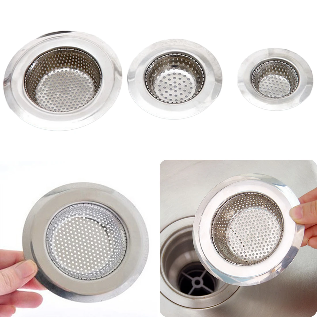
Is water collecting at the bottom of your fridge?
Luckily, both the cause and the solution to this problem is incredibly simple.
If you are getting water collecting in the bottom of your fridge or around the salad bin area, it’s almost certainly due to the drain hole being blocked.
Clearing the hole just needs a couple of pokes. Lastly, try not to let any food or produce you put into the fridge touch the back wet wall.
Not only can this cause drain hole blockages but it can also allow water to bypass the hole completely, and drain into your food instead.
ORDER NOW - Drain hole cleaning tool: https://parts.hotpoint.co.uk/product/...
To book a repair visit with one of our local engineers or to live chat with us visit: https://www.hotpointservice.co.uk/rep...
To purchase spare parts for any appliance visit:
https://parts.hotpoint.co.uk/?utm_sou...
For more hints & tips on all your Hotpoint kitchen appliances visit our channel: https://www.youtube.com/HotpointServi...
#Hotpointservice #Hotpoint
842 тыс. просмотров
8 лет назад
375 тыс. просмотров
2 года назад
968 тыс. просмотров
7 лет назад
226 тыс. просмотров
2 года назад
181 тыс. просмотров
6 лет назад
243 тыс. просмотров
2 года назад
1,3 млн просмотров
7 лет назад
134 тыс. просмотров
1 год назад
898 тыс. просмотров
4 года назад
3,3 тыс. просмотров
6 месяцев назад
295 тыс. просмотров
2 года назад
945 тыс. просмотров
2 года назад
1,2 тыс. просмотров
6 месяцев назад
207 тыс. просмотров
2 года назад
794 тыс. просмотров
6 лет назад
344 тыс. просмотров
4 года назад
923 тыс. просмотров
4 года назад
140 тыс. просмотров
6 месяцев назад
26 тыс. просмотров
1 год назад
56 тыс. просмотров
2 года назад
Вы не вошли в аккаунт
Вы с
https://www.sciencedirect.com/topics/engineering/drain-hole
https://www.youtube.com/watch?v=JOEODVb4a8o
Skyrim Apachii Hair Females
Mature Nl Free Porn
Small Boy Masturbating
Drain Hole - an overview | ScienceDirect Topics
How to unblock your fridge drain hole | by Hotpoint - YouTube
Orifice Plates with Drain Holes - NFOGM
What is Orifice Drain and Vent Hole ? - InstrumentationTools
Plants that (Don't) Need Drainage Holes: Here's the Truth
drain hole definition | English definition dictionary ...
How do you use a planter without drainage holes ...
How to Drill Holes in a Ceramic Pot: 3 Easy Steps!
drain hole - Deutsch-Übersetzung – Linguee Wörterbuch
Drain Hole