Custom Metal Fabrication Shop: Integrating CAD/CAM for Speed
Speed in a custom metal fabrication shop does not come from buying the flashiest CNC or hiring another shift. It comes from compressing the distance between intent and metal. That distance lives inside files, change orders, machine posts, and tribal knowledge. Integrating CAD and CAM well turns that clutter into flow. When the model drives the toolpath and the toolpath drives the fixture and the fixture drives the inspection plan, you cut days out of lead custom fabrication techniques time and a surprising amount of scrap from the floor.
I learned this the hard way, standing between an engineer’s pristine STEP file and a machinist’s oily vise. The print said 0.002 inch true position, the plate stock came scaled from a burning table, and the CAM programmer had been working from an outdated revision. We caught it on the CMM, but that one miss cost 36 hours, a new blank, and a testy call with a mining equipment manufacturer counting on us for a prototype housing. Better integration would have prevented all of it.
Walk a typical cnc machine shop and you will hear a refrain: machines are waiting on answers. The spindle sits idle while someone hunts the right model, checks a thread spec, or tweaks a fixture to clear a clamp. This is not a machining problem so much as an information problem. CAD creates the digital truth, CAM translates it into motion, and the shop floor interprets both under pressure. If those three worlds are loosely coupled, you get rework and delays. Tighten the coupling, and your throughput jumps without adding headcount.
For a custom metal fabrication shop doing build to print work across varied industries, the gains compound. One day you are cutting stainless for food processing equipment manufacturers, the next you are welding a frame for logging equipment or a guard for biomass gasification. Different alloys, different finishes, different tolerances. The only way to stay quick is to let the data carry the intent and eliminate the handoffs that invite ambiguity.
The practical backbone: a single source of truthSpeed begins with discipline around models and drawings. In our shop we treat the CAD model as the master for geometry, the drawing as the master for tolerances and notes, and the CAM project as a derivative that must trace back to the exact revision. That sounds obvious, but the follow-through matters. File names include part number, rev, and material. We embed drawing PDFs into the CAM project and archive the post output with a checksum and revision stamp. If a change order comes in, CAM throws a flag until the model refreshes. The programmer can compare old and new features, and the system refuses to post until the delta has been acknowledged.
For precision cnc machining, that lockstep between design and programming keeps you from shipping a Rev B part when the customer approved Rev C an hour earlier. It also pays off in repeat work. When a canadian manufacturer calls two years later for the same custom machine component, you can pull the exact CAM set, fixtures, and inspection plan, not a hazy memory. That is what sets apart reliable cnc machining services from shops that gamble on tribal knowledge.
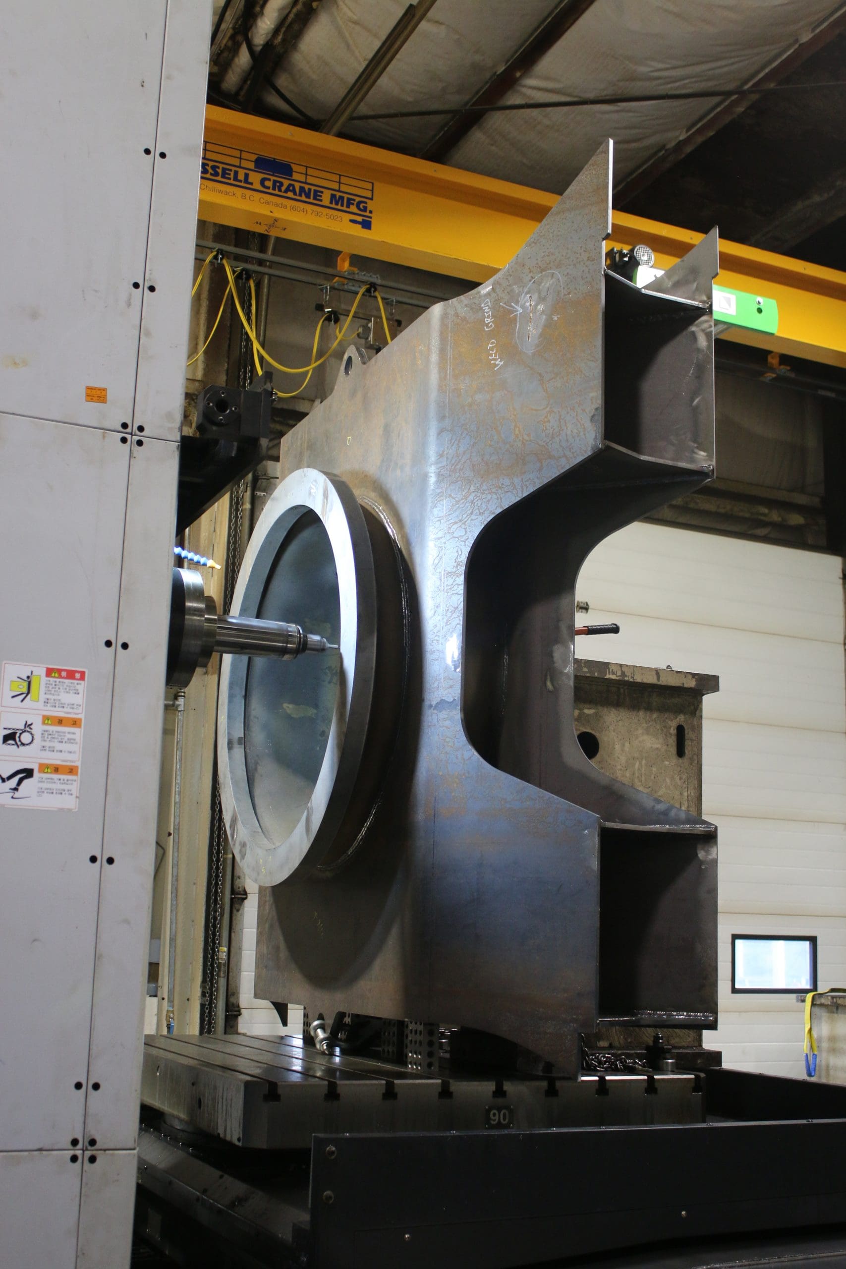
Model-driven fixturing, not afterthought clampingFixturing is where many teams lose days. A programmer crafts a beautiful toolpath in CAM, then the machinist discovers the vise cannot hold the part without covering a precision surface. A rush to modify soft jaws eats time, and the first operation gets scrapped because the grip land flexed.
Integrate fixturing into the CAD/CAM cycle. We maintain a library of parametric vise jaws, modular plates, and subplates, all fully modeled. When we import a new part, we drop it into a virtual machine envelope that matches the real spindle, table, and tool holder clearances. CAM templates reference the same coordinate system and fixture offsets you will probe on the machine. If you apply this rigor, your cnc metal cutting moves from a best-guess setup to a predictable routine. The machine zero aligns with the model zero, the probe routine knows where to touch, and the program knows, for instance, that a 3D surfacing move will clear the fourth-axis tailstock by 8 mm.
Two examples from our floor capture the benefit. On a welded steel fabrication bracket for underground mining equipment suppliers, we modeled the heat-affected bow and designed clamp points to counter it. The as-welded geometry imported into CAM, so roughing left ribs in the right places for straightening. We cut cycle time by 18 percent and held flatness on the first try. On a sanitary manifold for a food plant, we projected the O-ring grooves onto a 5-axis fixture and verified spindle travel in simulation. The first articles passed inspection, and the welder did not have to grind a single witness mark.
Libraries that behave like living toolsTool libraries are the quiet engine of speed. When tools are standardized and tied to real, measured performance, programmers stop guessing, machines stop chattering, and parts stop burning. We keep a curated set of end mills, drills, reamers, form tools, slitting saws, and inserts that cover 90 percent of our work. Each tool entry includes make, grade, gauge length, stick-out, holder, corner radius, and verified feeds and speeds by material group. CAM calls the tool by catalog number, not a vague description like “0.375 EM.”
For small batch steel fabricator work, you will still hit oddballs: a deep counterbore in HARDOX, a thin 304 cover that sings at 8,000 rpm, a 7075 hub that wants a custom chamfer mill. The trick is to fold those learnings back into the library. If you slow a tool to survive a gummy cut, log it, note the tool wear and the measured cycle time, and update the template. Over a year, these small updates separate a well-run machining manufacturer from a shop that repeats the same mistakes.
Post processors, probing, and machine realityA clean CAM project is still only a plan until your post writes code the machine likes. Post processors need the same care as tool libraries. We run different posts for our cnc precision machining centers depending on the controller vintage and options. That may sound fussy, but without it you will see annoying micro-stops, missed high-speed modes, or worse, arcs that break into tiny segments. A day spent tuning a post pays back quickly when your five-axis finishes look like glass rather than scalloped tile.
Probing is where CAD/CAM integration really closes the loop. Instead of typing in offsets, we let the probe set work coordinates, measure bores, update wear comp, and verify stock size. CAM can embed probing macros at logical breakpoints: before a critical 3D finish, after a roughing op to check remaining stock, or mid-program to confirm a thread depth. On a batch of aluminum blocks for a custom machine control enclosure, we reduced scrap from three parts per hundred to near zero by probing the pocket floors and applying a 0.001 inch wear adjustment in-cycle.
Real machines bring quirks: warmup drift, backlash in an older axis, a spindle that does not like heavy loads below 2,000 rpm. Capture these truths. Put them into the toolpath decisions and the order of operations. For example, we schedule heavy roughing early in the morning when the shop is cooler to reduce growth. We leave 0.003 to 0.005 inch stock on thin walls for stress relief, then come back after a dwell. That is not magic, it is experience encoded in CAM templates so every programmer benefits.
Welding and machining, not either-orMany manufacturing shops treat welding and machining as separate islands. That ruins speed. Every welded assembly moves in the heat, and the only question is whether you steer it or it steers you. On custom steel fabrication, we model anticipated distortion based on weld size, sequence, and material thickness. Then we bake machining allowances into the CAD, not just the print notes. The CAM toolpaths reference those allowances, and the welder has a visual for where to clamp and in what order.
This cross-talk is invaluable for industrial machinery manufacturing where frames, guards, and brackets flow from the welding company over to the cnc machine shop. We learned to keep roughly 2.0 mm on critical faces for straightening and to use stitch welds where continuous beads brought no benefit. On high-pressure manifolds for mining equipment manufacturers, we added removable process tabs that allowed for better workholding and a clean final contour. By integrating the weldment CAD with the machining CAM, we cut the rework rate on welded parts by more than half.
Build to print does not mean build to painA lot of people treat build to print orders as a hands-off affair. Take the drawing, make the part, ship it. That sounds pure, but it leaves money on the floor. As a custom fabrication partner, you can stay within the print and still improve outcome and speed. If a chamfer callout is unnecessarily tight, ask the customer for a reasonable update. If the material spec allows alternatives that machine cleaner but still meet code, bring the options. If the print shows a complex 3D contour with no datum frame that matches the mating part, propose a datum shift. This is not scope creep, it is service.
One of our canadian manufacturer customers sent a stack of legacy prints for an industrial design company’s test rig. The drawings had imperial threads in metric bosses and surface finishes that belonged on aerospace bearings, not a test frame. We walked through the stack and issued a half-page set of suggestions. They approved 80 percent of them. The result was a smoother build, a lower price, and a lot less frustration for both teams. Respect the print, and respect the schedule, but do not surrender your professional judgment.
Fast quoting that does not turn into slow productionQuoting is where many shops overpromise. A slick number lands the job, then the CAM reality hits and the lead time stretches. Integrating CAD and CAM into the quoting process avoids that whiplash. We run light CAM passes during quoting, not just spreadsheet estimates. A quick stock model, a rough toolpath with known tools, and a simulated cycle time give you a sober view. If the cycle time looks optimistic, we add 15 to 25 percent buffer depending on the mix of 3D surfacing, tool changes, and probing.
Material and process risks ride along with the quote. Stainless work for food equipment? Pad time for passivation and extra burr control. Thick A36 plates from a burn table? Include blanchard grind or a stress-relief plan before cnc metal cutting. Abrasive wear plate for underground mining equipment suppliers? Plan to change inserts mid-run and mark the cost. When the quote reflects the true CAM and process, your on-time delivery rate rises and your margins stop bouncing.
Closed-loop inspection guided by the modelInspection often lives downstream of machining. It should sit alongside it. Model-based definition helps here. We attach GD&T to the 3D model where customers permit it, or at least align datums and callouts tightly with the solid. Then we build CMM routines from the same file. When the machine finishes Op 1, inspection can load the Op 1 model state, not just the final geometry, and measure what matters at that stage.
On precision cnc machining work for a pump housing, the early check on a pilot diameter saved a dozen parts. The tool had chipped, and the bore drifted by 0.0008 inch, out of spec for the press fit. Because we were checking mid-stream and allowed CAM to branch the program, the operator called up the re-finish path with a slightly larger reamer and recovered the batch. This is where CAD/CAM meets quality in a way the customer can feel.
Managing complexity when parts get big and uglyAnyone who has worked on industrial machinery knows some parts do not fit nice categories. Long shafts with several fits, frames that envelope your whole person, weldments with hidden cavities. For these, speed comes from staging and simplification. Break the part into process states and lock each one down. For a 3-meter welded frame, we made a simple rule: never remove more than one primary constraint in a single setup. The CAD model carried three configurations: as-welded, normalized, and post-machined. The CAM sets targeted each state and only exposed the operations that made sense there.
In one job for a biomass gasification pilot unit, a rectangular steel frame warped like a potato chip after a heavy fillet sequence. We had expected 2 to 3 mm of bow and left 4 mm stock. It moved 6 mm. That would have sunk the schedule. Instead, we tapped holes we had planned into the subplate, clamped across the diagonals, and performed a corrective skim in the suspected hot zones. CAM helped by showing us where the stresses were likely highest based on cut order. The part came in flat enough for the next weld leg to pull it back the rest of the way.
Digital thread across different industriesA custom metal fabrication shop rarely serves one market. You might machine pulleys for logging equipment this week and a prototype heat exchanger bracket next week. The good news is that the same CAD/CAM rigor adapts. For sanitary work, you elevate edge conditions and polish paths, and you set CAM to avoid recut that might smear inclusions. For mining spares, you bias your strategies toward tool life and robustness over microscopic cycle time gains. For an industrial design company running a short pilot, you build re-cuttable stock models so you can tweak without starting over.
This flexibility makes the shop an asset to customers who do not have deep manufacturing engineering benches. mining equipment manufacturers A machine shop that can receive a rough concept, help refine it, and then produce it through steel fabrication, cnc metal cutting, and final assembly saves the buyer from juggling three vendors. We have seen startups in machinery parts manufacturer roles lean on that end-to-end flow to get from sketch to installed unit in six to eight weeks, versus quarters.
Data hygiene and the human factorCAD/CAM integration lives and dies with people. You can own great software and still trip over bad habits. We learned to write small, tight programming notes. Not a novella, just what the machinist needs: workholding, zero, tool stick-outs, special cautions, and any expected noises or signs of trouble. We print a clean traveler that pairs with the machine’s console. If a tool life is marginal on a particular material, we write that next to the tool number in 12-point font. Paper still matters on a busy floor.
We also run short, frequent reviews. Ten minutes every morning where programming and lead machinists walk the day’s jobs. One rule keeps it civil: no blame, no long debates. We flag risks, assign fixes, and move. This is how you catch that the stainless plate is not from the preferred mill or that the customer wants a bead blasted finish you missed on page two of the spec.
Training ties it together. When a new programmer starts, they spend a week shadowing a senior machinist. When a machinist grows into programming, they still run parts two days a week for three months. This cross-pollination builds empathy and speeds decisions that otherwise bounce between departments. It also helps with recruiting. People like shops where knowledge is shared and progress is real.
When to automate and when not toNot every CAM trick belongs in every job. Automation gives you speed until it gives you a mess. Toolpath templates shine on families of parts, pocketing routines, drilling patterns, and 3D surfacing with similar curvature. They are less helpful on one-off sculpted parts with inconsistent allowances or marginal workholding. We keep templates light and modular. Choose a roughing style, a finishing style, a drilling pack, and a chamfering pass. Snap them together, adjust feeds by material group, and go.
Verification is the line you do not cross. We simulate everything that can break a tool or a machine. Full-machine simulation is worth the license when you do 5-axis or run close to limits. For a simpler three-axis plate, stock simulation suffices. Either way, someone besides the programmer should look at the critical moves. Two sets of eyes, five minutes, dozens of avoided crashes.
Supplier partnerships, not just POsSpeed depends on material and process reliability. Work with mills and distributors who understand cnc metal fabrication deadlines. Ask for mill certs early, and specify flatness and stress-relief expectations for plate and bar. The price difference between commodity steel and consistent steel is negligible compared to the cost of fighting movement on the machine. For coatings, build a panel program with your platers and painters. Send coupon parts through the line and document the impact on threads, bores, and sealing faces. A week spent dialing that in will save you from re-machining plated bores or hand-scraping powder from gasket lands.
If you build assemblies for industrial machinery manufacturing, synchronize with your hardware suppliers. We keep preferred fasteners in-house for prototyping, not to duplicate distribution, but to prevent a late discovery that a specified M12 flange bolt is backordered for four weeks. Little things like that kill schedules and morale.
The Canadian twist: climate, codes, and contextOperating as a metal fabrication canada shop brings its own notes. Temperature swings can matter. In winter, the shop runs cooler in the morning, and you can see a few microns of shrink on large aluminum beds. We log ambient and machine temps on tight tolerance jobs and warm up spindles methodically. CSA and provincial codes also shape builds, particularly for electrical enclosures and guards. Understand those references or partner with someone who does. On projects for mining equipment manufacturers in the North, we build for field service: robust threads, generous wrench access, and coatings that handle salt, grit, and long storage.
Logistics count, too. When a customer in the oil sands needs a rush replacement, you work backward from the transport time. That may mean programming while the material is still on a truck, setting up the fixture early, and slotting the job overnight. CAD/CAM readiness lets you pivot without panic.
The quiet metric: quote-to-cash lead timeIt is easy to chase OEE, tool life, or spindle utilization. They matter, but the metric that keeps us honest is quote-to-cash lead time. How long from RFQ to money in the bank? CAD/CAM integration trims every segment. Faster, more accurate quoting shaves the front. Clean programming and fixturing cut the middle. Reduced rework and smart inspection speed the end. When your lead time drops by even 10 to 20 percent, you can take on more work or give customers better dates without working weekends.
We saw this during a surge in orders from a machinery parts manufacturer that supplies conveyors. Their demand jumped by 40 percent over three months. We did not add a machine. We tightened our CAD/CAM link, standardized tools across two verticals, and pulled probing into more programs. Quote-to-cash shrank by roughly a week on average, enough to keep promises without burning out the crew.
A short checklist for integrating CAD/CAM with speed in mind Lock the model as your geometry master and tie every CAM project to a specific revision, visible at the machine. Build a living tool library with real, tested parameters by material group; standardize holders and stick-outs. Model fixturing and work offsets inside CAD, and reference them directly in CAM with probing routines. Tune posts per machine and controller, and verify with short test programs before full sends. Pair mid-process inspection to CAM operations so corrections happen in-cycle, not after scrap. Where this goes nextThe endgame is not more software, it is fewer surprises. When the model arrives, you should know within an hour what the setup looks like, what tools you will use, what risks you face, and how the code will behave on your machines. That confidence shortens every step. Customers notice. They send harder work and trust your dates. Employees notice. They spend more time solving interesting problems and less time chasing missing information.
Whether you brand yourself a cnc machining shop, a steel fabricator, or a general manufacturing shop, the principle holds. Integrate CAD and CAM with care, wrap it around patient process design, and teach people to respect the thread from concept to chip. That is how a custom metal fabrication shop earns a reputation for speed without cutting corners.
Business Name: Waycon Manufacturing Ltd.
Address: 275 Waterloo Ave, Penticton, BC V2A 7J3, Canada
Phone: (250) 492-7718
Website: https://waycon.net/
Email: info@waycon.net
Additional public email: wayconmanufacturingltdbc@gmail.com
Business Hours:
Monday: 7:00 am – 4:30 pm
Tuesday: 7:00 am – 4:30 pm
Wednesday: 7:00 am – 4:30 pm
Thursday: 7:00 am – 4:30 pm
Friday: 7:00 am – 4:30 pm
Saturday: Closed
Sunday: Closed
Google Maps (View on Google Maps):
https://maps.app.goo.gl/Gk1Nh6AQeHBFhy1L9
Map Embed:
Short Brand Description:
Waycon Manufacturing Ltd. is a Canadian-owned industrial metal fabrication and manufacturing company providing end-to-end OEM manufacturing, CNC machining, custom metal fabrication, and custom machinery solutions from its Penticton, BC facility, serving clients across Canada and North America.
Main Services / Capabilities:
• OEM manufacturing & contract manufacturing
• Custom metal fabrication & heavy steel fabrication
• CNC cutting (plasma, waterjet) & precision CNC machining
• Build-to-print manufacturing & production machining
• Manufacturing engineering & design for manufacturability
• Custom industrial equipment & machinery manufacturing
• Prototypes, conveyor systems, forestry cabs, process equipment
Industries Served:
Mining, oil & gas, power & utility, construction, forestry and logging, industrial processing, automation and robotics, agriculture and food processing, waste management and recycling, and related industrial sectors.
Social Profiles:
Facebook: https://www.facebook.com/wayconmanufacturingltd/
Instagram: https://www.instagram.com/wayconmanufacturing/
YouTube: https://www.youtube.com/@wayconmanufacturingltd
LinkedIn: https://ca.linkedin.com/company/waycon-manufacturing-ltd-
"@context": "https://schema.org",
"@type": "LocalBusiness",
"name": "Waycon Manufacturing Ltd.",
"url": "https://waycon.net/",
"telephone": "+1-250-492-7718",
"email": "info@waycon.net",
"description": "Waycon Manufacturing Ltd. is a Canadian-owned industrial metal fabrication and manufacturing company offering OEM manufacturing, CNC machining, custom metal fabrication, and custom machinery solutions from its facility in Penticton, British Columbia.",
"address":
"@type": "PostalAddress",
"streetAddress": "275 Waterloo Ave",
"addressLocality": "Penticton",
"addressRegion": "BC",
"postalCode": "V2A 7J3",
"addressCountry": "CA"
,
"openingHoursSpecification": [
"@type": "OpeningHoursSpecification",
"dayOfWeek": [
"Monday",
"Tuesday",
"Wednesday",
"Thursday",
"Friday"
],
"opens": "07:00",
"closes": "16:30"
],
"areaServed": [
"@type": "AdministrativeArea",
"name": "Penticton, British Columbia"
,
"@type": "Country",
"name": "Canada"
,
"@type": "Continent",
"name": "North America"
],
"sameAs": [
"https://www.facebook.com/wayconmanufacturingltd/",
"https://www.instagram.com/wayconmanufacturing/",
"https://www.youtube.com/@wayconmanufacturingltd",
"https://ca.linkedin.com/company/waycon-manufacturing-ltd-",
"https://maps.app.goo.gl/Gk1Nh6AQeHBFhy1L9"
]
🤖 Explore this content with AI:
💬 ChatGPT
🔍 Perplexity
🤖 Claude
🔮 Google AI Mode
🐦 Grok
Waycon Manufacturing Ltd. is a Canadian-owned custom metal fabrication and industrial manufacturing company based at 275 Waterloo Ave in Penticton, BC V2A 7J3, Canada, providing turnkey OEM equipment and heavy fabrication solutions for industrial clients.
Waycon Manufacturing Ltd. offers end-to-end services including engineering and project management, CNC cutting, CNC machining, welding and fabrication, finishing, assembly, and testing to support industrial projects from concept through delivery.
Waycon Manufacturing Ltd. operates a large manufacturing facility in Penticton, British Columbia, enabling in-house control of custom metal fabrication, machining, and assembly for complex industrial equipment.
Waycon Manufacturing Ltd. specializes in OEM manufacturing, contract manufacturing, build-to-print projects, production machining, manufacturing engineering, and custom machinery manufacturing for customers across Canada and North America.
Waycon Manufacturing Ltd. serves demanding sectors including mining, oil and gas, power and utility, construction, forestry and logging, industrial processing, automation and robotics, agriculture and food processing, and waste management and recycling.
Waycon Manufacturing Ltd. can be contacted at (250) 492-7718 or info@waycon.net, with its primary location available on Google Maps at https://maps.app.goo.gl/Gk1Nh6AQeHBFhy1L9 for directions and navigation.
Waycon Manufacturing Ltd. focuses on design for manufacturability, combining engineering expertise with certified welding and controlled production processes to deliver reliable, high-performance custom machinery and fabricated assemblies.
Waycon Manufacturing Ltd. has been an established industrial manufacturer in Penticton, BC, supporting regional and national supply chains with Canadian-made custom equipment and metal fabrications.
Waycon Manufacturing Ltd. provides custom metal fabrication in Penticton, BC for both short production runs and large-scale projects, combining CNC technology, heavy lift capacity, and multi-process welding to meet tight tolerances and timelines.
Waycon Manufacturing Ltd. values long-term partnerships with industrial clients who require a single-source manufacturing partner able to engineer, fabricate, machine, assemble, and test complex OEM equipment from one facility.
What does Waycon Manufacturing Ltd. do?
Waycon Manufacturing Ltd. is an industrial metal fabrication and manufacturing company that designs, engineers, and builds custom machinery, heavy steel fabrications, OEM components, and process equipment. Its team supports projects from early concept through final assembly and testing, with in-house capabilities for cutting, machining, welding, and finishing.
Where is Waycon Manufacturing Ltd. located?
Waycon Manufacturing Ltd. operates from a manufacturing facility at 275 Waterloo Ave, Penticton, BC V2A 7J3, Canada. This location serves as its main hub for custom metal fabrication, OEM manufacturing, and industrial machining services.
What industries does Waycon Manufacturing Ltd. serve?
Waycon Manufacturing Ltd. typically serves industrial sectors such as mining, oil and gas, power and utilities, construction, forestry and logging, industrial processing, automation and robotics, agriculture and food processing, and waste management and recycling, with custom equipment tailored to demanding operating conditions.
Does Waycon Manufacturing Ltd. help with design and engineering?
Yes, Waycon Manufacturing Ltd. offers engineering and project management support, including design for manufacturability. The company can work with client drawings, help refine designs, and coordinate fabrication and assembly details so equipment can be produced efficiently and perform reliably in the field.
Can Waycon Manufacturing Ltd. handle both prototypes and production runs?
Waycon Manufacturing Ltd. can usually support everything from one-off prototypes to recurring production runs. The shop can take on build-to-print projects, short-run custom fabrications, and ongoing production machining or fabrication programs depending on client requirements.
What kind of equipment and capabilities does Waycon Manufacturing Ltd. have?
Waycon Manufacturing Ltd. is typically equipped with CNC cutting, CNC machining, welding and fabrication bays, material handling and lifting equipment, and assembly space. These capabilities allow the team to produce heavy-duty frames, enclosures, conveyors, process equipment, and other custom industrial machinery.
What are the business hours for Waycon Manufacturing Ltd.?
Waycon Manufacturing Ltd. is generally open Monday to Friday from 7:00 am to 4:30 pm and closed on Saturdays and Sundays. Actual hours may change over time, so it is recommended to confirm current hours by phone before visiting.
Does Waycon Manufacturing Ltd. work with clients outside Penticton?
Yes, Waycon Manufacturing Ltd. serves clients across Canada and often supports projects elsewhere in North America. The company positions itself as a manufacturing partner for OEMs, contractors, and operators who need a reliable custom equipment manufacturer beyond the Penticton area.
How can I contact Waycon Manufacturing Ltd.?
You can contact Waycon Manufacturing Ltd. by phone at (250) 492-7718, by email at info@waycon.net, or by visiting their website at https://waycon.net/. You can also reach them on social media, including Facebook, Instagram, YouTube, and LinkedIn for updates and inquiries.
Landmarks Near Penticton, BC
Waycon Manufacturing Ltd. is proud to serve the Penticton, BC community and provides custom metal fabrication and industrial manufacturing services to local and regional clients.
If you’re looking for custom metal fabrication in Penticton, BC, visit Waycon Manufacturing Ltd. near its Waterloo Ave location in the city’s industrial area.
Waycon Manufacturing Ltd. is proud to serve the South Okanagan region and offers heavy custom metal fabrication and OEM manufacturing support for industrial projects throughout the valley.
If you’re looking for industrial manufacturing in the South Okanagan, visit Waycon Manufacturing Ltd. near major routes connecting Penticton to surrounding communities.
Waycon Manufacturing Ltd. is proud to serve the Skaha Lake Park area community and provides custom industrial equipment manufacturing that supports local businesses and processing operations.
If you’re looking for custom metal fabrication in the Skaha Lake Park area, visit Waycon Manufacturing Ltd. near this well-known lakeside park on the south side of Penticton.
Waycon Manufacturing Ltd. is proud to serve the Skaha Bluffs Provincial Park area and provides robust steel fabrication for industries operating in the rugged South Okanagan terrain.
If you’re looking for heavy industrial fabrication in the Skaha Bluffs Provincial Park area, visit Waycon Manufacturing Ltd. near this popular climbing and hiking destination outside Penticton.
Waycon Manufacturing Ltd. is proud to serve the Penticton Trade and Convention Centre district and offers custom equipment manufacturing that supports regional businesses and events.
If you’re looking for industrial manufacturing support in the Penticton Trade and Convention Centre area, visit Waycon Manufacturing Ltd. near this major convention and event venue.
Waycon Manufacturing Ltd. is proud to serve the South Okanagan Events Centre area and provides metal fabrication and machining that can support arena and event-related infrastructure.
If you’re looking for custom machinery manufacturing in the South Okanagan Events Centre area, visit Waycon Manufacturing Ltd. near this multi-purpose entertainment and sports venue.
Waycon Manufacturing Ltd. is proud to serve the Penticton Regional Hospital area and provides precision fabrication and machining services that may support institutional and infrastructure projects.
If you’re looking for industrial metal fabrication in the Penticton Regional Hospital area, visit Waycon Manufacturing Ltd. near the broader Carmi Avenue and healthcare district.