Cone Penetration

🛑 👉🏻👉🏻👉🏻 INFORMATION AVAILABLE CLICK HERE👈🏻👈🏻👈🏻
The cone penetration or cone penetrometer test (CPT) is a method used to determine the geotechnical engineering properties of soils and delineating soil stratigraphy. It was initially developed in the 1950s at the Dutch Laboratory for Soil Mechanics in Delft to investigate soft soils. Based on this history it has also been called the "Dutch cone test". Today, the CPT is one of the most used and accepted soil methods for soil investigation worldwide.
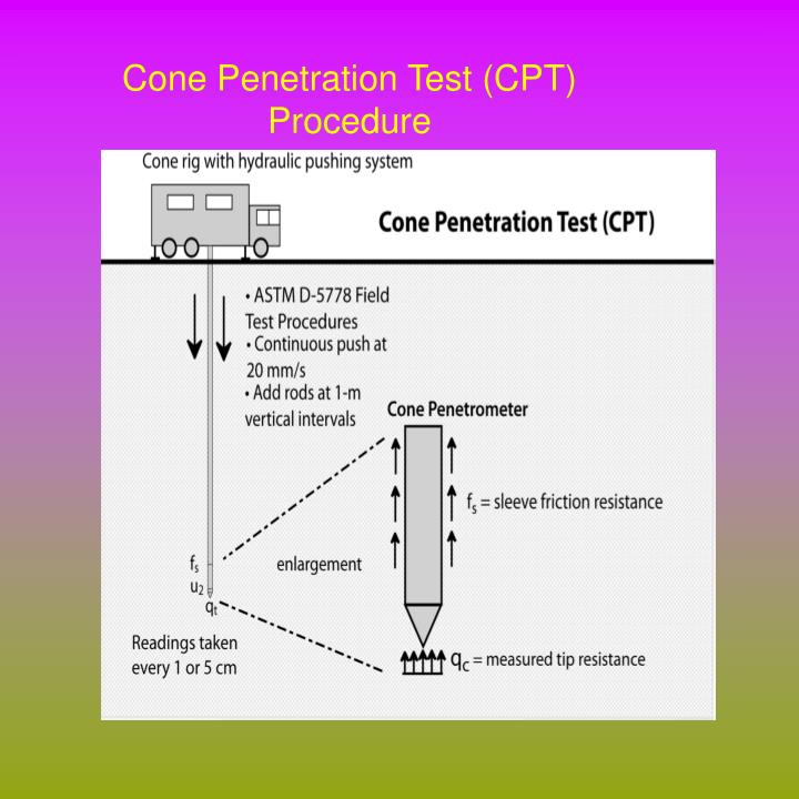
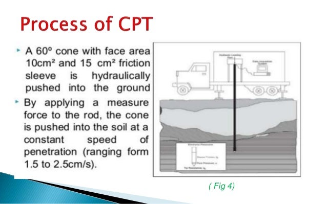
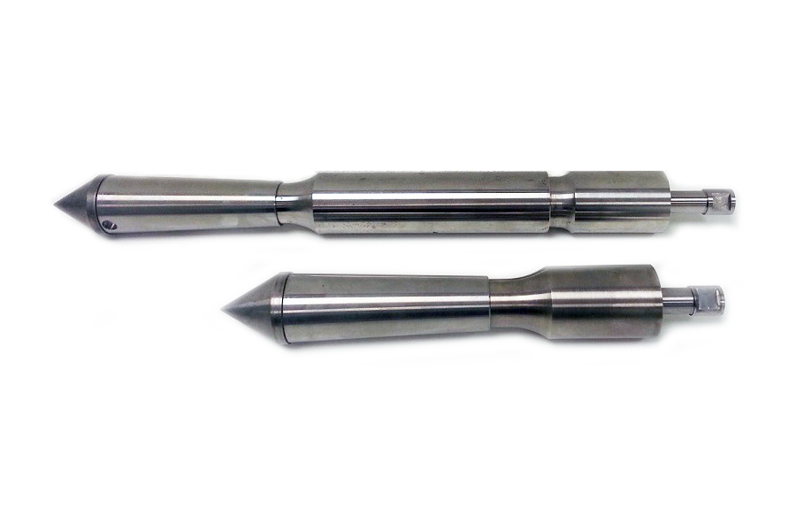
The test method consists of pushing an instrumented cone, with the tip facing down, into the ground at a controlled rate (controlled between 1.5 -2.5 cm/s accepted). The resolution of the CPT in delineating stratigraphic layers is related to the size of the cone tip, with typical cone tips having a cross-sectional area of either 10 or 15 cm², corresponding to diameters of 3.6 and 4.4 cm. A very early ultra-miniature 1 cm² subtraction penetrometer was developed and used on a US mobile ballistic missile launch system (MGM-134 Midgetman) soil/structure design program in 1984 at the Earth Technology Corporation of Long Beach, California.
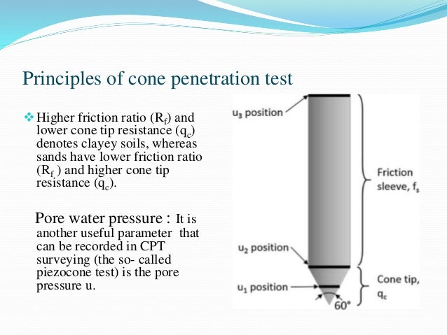
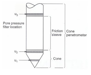
The early applications of CPT mainly determined the logistics of soil geotechnical property of bearing capacity. The original cone penetrometers involved simple mechanical measurements of the total penetration resistance to pushing a tool with a conical tip into the soil. Different methods were employed to separate the total measured resistance into components generated by the conical tip (the "tip friction") and friction generated by the rod string. A friction sleeve was added to quantify this component of the friction and aid in determining soil cohesive strength in the 1960s.[1] Electronic measurements began in 1948 and improved further in the early 1970s.[2] Most modern electronic CPT cones now also employ a pressure transducer with a filter to gather pore water pressure data. The filter is usually located either on the cone tip (the so-called U1 position), immediately behind the cone tip (the most common U2 position) or behind the friction sleeve (U3 position). Pore water pressure data aids determining stratigraphy and is primarily used to correct tip friction values for those effects. CPT testing which also gathers this piezometer data is called CPTU testing. CPT and CPTU testing equipment generally advances the cone using hydraulic rams mounted on either a heavily ballasted vehicle or using screwed-in anchors as a counter-force. One advantage of CPT over the Standard Penetration Test (SPT) is a more continuous profile of soil parameters, with data recorded at intervals typically of 20 cm but as small as 1 cm.
Manufacturers of cone penetrometer probes and data acquisition systems include Hogentogler, which has been acquired by the Vertek Division of Applied Research Associates,[3][4] GeoPoint Systems BV[5] and Pagani Geotechnical Equipment.[6]
In addition to the mechanical and electronic cones, a variety of other CPT-deployed tools have been developed over the years to provide additional subsurface information. One common tool advanced during CPT testing is a geophone set to gather seismic shear wave and compression wave velocities. This data helps determine the shear modulus and Poisson's ratio at intervals through the soil column for soil liquefaction analysis and low-strain soil strength analysis. Engineers use the shear wave velocity and shear modulus to determine the soil's behavior under low-strain and vibratory loads. Additional tools such as laser-induced fluorescence, X-ray fluorescence,[7] soil conductivity/resistivity,[8] pH, temperature and membrane interface probe and cameras for capturing video imagery are also increasingly advanced in conjunction with the CPT probe.
An additional CPT deployed tool used in Britain, Netherlands, Germany, Belgium and France is a piezocone combined with a tri-axial magnetometer. This is used to attempt to ensure that tests, boreholes, and piles, do not encounter unexploded ordnance (UXO) or duds. The magnetometer in the cone detects ferrous materials of 50 kg or larger within a radius of up to about 2 m distance from the probe depending on the material, orientation and soil conditions.
CPT for geotechnical applications was standardized in 1986 by ASTM Standard D 3441 (ASTM, 2004). ISSMGE provides international standards on CPT and CPTU. Later ASTM Standards have addressed the use of CPT for various environmental site characterization and groundwater monitoring activities.[9][10][11] For geotechnical soil investigations, CPT is more popular compared to SPT as a method of geotechnical soil investigation. Its increased accuracy, speed of deployment, more continuous soil profile and reduced cost over other soil testing methods. The ability to advance additional in situ testing tools using the CPT direct push drilling rig, including the seismic tools described above, are accelerating this process.
^ Begemann, H. K. S, 1965, "The Friction Jacket Cone as an Aid in Determining the Soil Profile"; Proceedings, 6th ICSMFE, Montreal, Quebec, Canada, Vol I, pp.17-20.
^ De Reister, J., 1971, "Electric Penetrometer for Site Investigations"; Journal of SMFE Division, ASCE, Vol. 97, SM-2, pp. 457-472.
^ "CPT Equipment". Hogentogler & Co., Inc. Archived from the original on March 4, 2016.
^ "CPT Cones and Data Acquisition Systems - Vertek CPT". Applied Research Associates, Inc. 2016.
^ "Geopoint.nl". Geopoint Systems BV. 2016.
^ "CPT - Cones and Acquisition Systems". Pagani Geotechnical Equipment. 2015.
^ "Home | Chemistry Division". chemistry.nrl.navy.mil. Retrieved 2015-04-20.
^ Strutynsky, A.I., R. Sandiford, D. Cavaliere, 1991. Use of Piezometric Cone Penetration Testing with Electrical Conductivity Measurements (CPTU-EC) for Detection of Hydrocarbon Contamination in Saturated Granular Soils. Current Practices in Ground Water and Vadose Zone Investigations, ASTM
^ ASTM 6001
^ ASTM 6067
^ Strutynsky, A.I., T. Sainey, 1990. Use of the Piezometric Cone Penetration Test and Penetrometer Groundwater Sampling for Volatile Organic Contaminant Plume Detection. Petroleum Hydrocarbons and Organic Chemicals in Groundwater: Prevention, Detection and Restoration. API/NWWA
Content is available under CC BY-SA 3.0 unless otherwise noted.
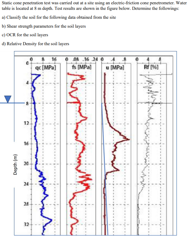
Cone Penetration Tests (CPT) are performed in two different points: the North side of the building and the South side.
Jean M. Audibert, Jun Huang, in Handbook of Offshore Engineering, 2005
The CPT device and its peripheral systems are mounted onto a standard ROV tooling skid (fig. 16.51). A Work-class ROV is then attached to the skid and the CPT and its sub-systems take their power from the vehicle's supply.
The 1 m long CPT push rod is thrust into the soil by a hydraulic ram. Due to the limited reactive force provided by an ROV, the CPT's cone area is reduced to 5 cm2.
The water depth capabilities of ROV CPTs are often only limited by the capacity of the vehicle. Hence, deployment down to 3000 m is quite feasible, although 1500 m is more the norm.
URL: https://www.sciencedirect.com/science/article/pii/B9780080443812500230
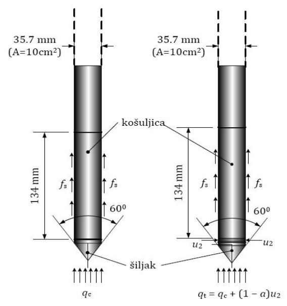
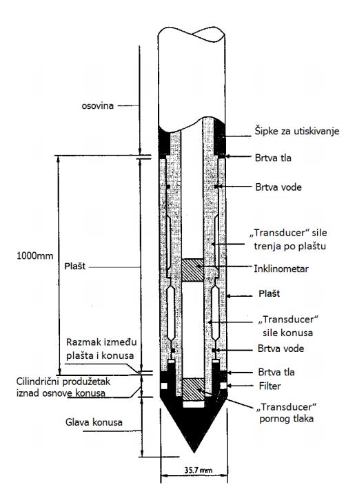
The cone penetration test (CPT) was invented and developed in Europe but has gained increasing importance in other parts of the world, especially in connection with soil compaction projects. Different types of mechanical and electric cone penetrometers exist, but the electric cone is most widely used. A steel rod with a conical tip (an apex angle of 60° and a diameter of 35.7 mm) is pushed at a rate of 2 cm/s into the soil. The steel rod has the same diameter as the cone.
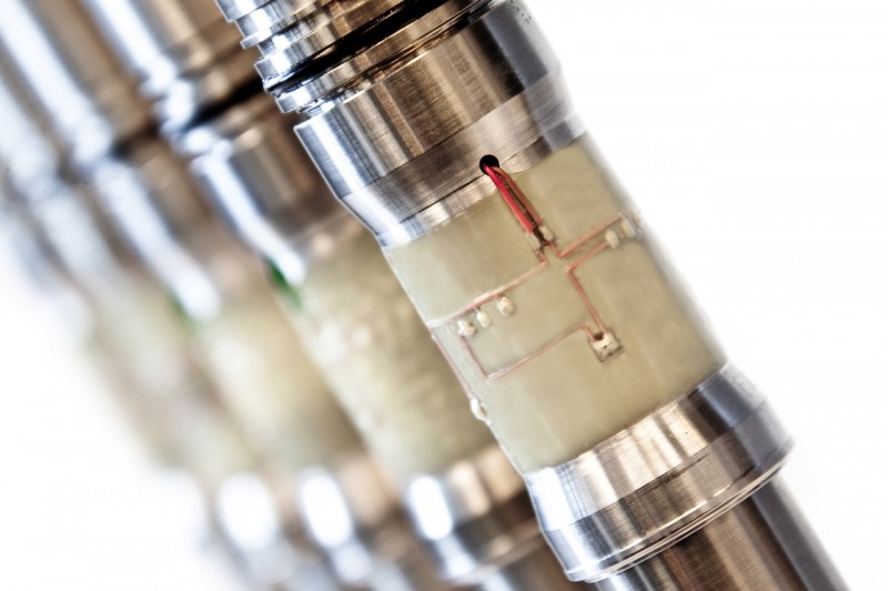
The penetration resistance at the tip and along a section of the shaft (friction sleeve) is measured. The friction sleeve is located immediately above the cone and has a surface area of 15,000 mm2. The electric CPT is provided with transducers to record the cone resistance and the local friction sleeve.
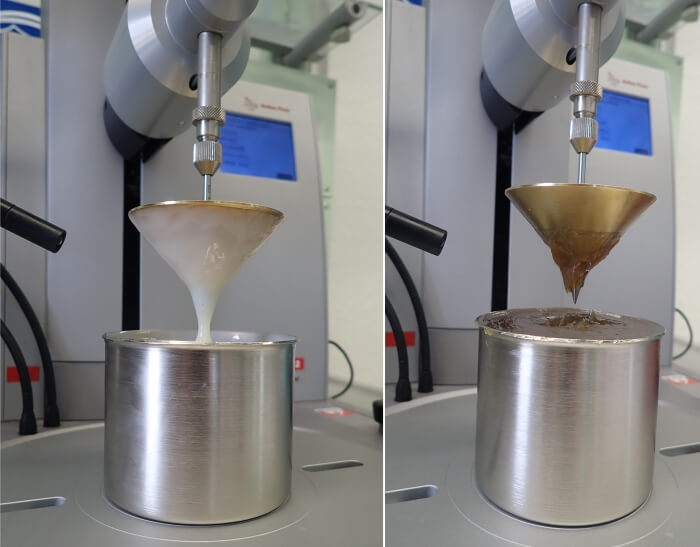
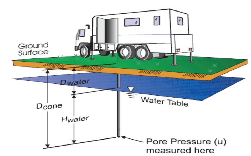
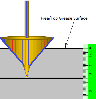
A CPT probe equipped with a pore-water pressure sensor is called a CPTU. It is important to assure complete saturation of the filter ring of the pore-water (piezo) element as shown in Fig. 8.3. Otherwise, the response of the piezo-transducer, which registers the variation of pore water pressure during penetration, will be slow and may give erroneous results. The CPTU offers the possibility to determine hydraulic soil properties (such as hydraulic conductivity–permeability), but it is most widely used for identification of soil type and soil stratification.
The CPT can also be equipped with other types of sensors, including vibration sensors (an accelerometer or geophone) for determination of vibration acceleration or velocity. The “seismic cone” is not yet used on a routine basis, but because of the relative simplicity of the test, it has potential for wider application especially on soil compaction projects.
The CPT is standardized, and the measurements are less operator-dependent than the SPT, thus giving more reproducible results. The implementation of the CPT is presented in Fig. 8.4.
The CPT measures the cone resistance (qc) and the sleeve friction (fs) from which the friction ratio FR can be determined. FR is the ratio between the local sleeve friction and the cone resistance, expressed as a percentage (fs/qc). In spite of the limited accuracy of sleeve friction measurements, the valuable information which can be obtained in connection with compaction projects has not yet been fully appreciated. As will be discussed later, the sleeve friction measurement reflects the variation of lateral earth pressure in the ground, and can be used to investigate the effect of soil compaction on the state of stress. Cone and sleeve friction measurements are also strongly affected by the effective overburden pressure. It is necessary to take this effect into account, similar to the SPT.
One important objective of the CPT investigations in connection with soil compaction is to obtain information concerning soil stratification and variation in soil properties both in horizontal and vertical directions. The friction ratio is often used as an indicator of soil type (grain size) and can provide valuable information when evaluating alternative compaction methods.
Measurement of the excess pore water pressure with the CPTU can detect layers and seams of fine-grained material (silt and clay). It is also possible to obtain more detailed data concerning soil permeability and thus soil stratification.
URL: https://www.sciencedirect.com/science/article/pii/B9780081019443000085
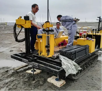
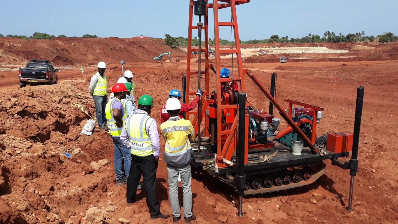
The CPT tanks used to advance the cone into the ground mainly consist of a hydraulic jack and a reaction system. In some cases, other equipment such as an anchored auger is incorporated as well. The axial bearing capacity required for the test varies typically between 100 and 200 kN. However, there are also some systems with capacity ranging from 20 to 50 kN, which can be employed in soft soils.
The CPT tanks are usually placed in a truck weighing 15 ton or more, and torsional anchors can be implemented to provide the required reaction force. The power for the hydraulic jack is supplied by the truck's motor. The electrical equipment and computers needed for recording the test's measurements are located inside of the truck to provide an appropriate condition for monitoring the temperature and suitable protection of the electrical equipment. Different examples of CPT rigs and trucks are shown in Fig. 3.6.
Figure 3.6. Examples of cone penetration test trucks (Robertson and Cabal, 2010).
A 20-ton penetrating system usually provides an insertion down to a depth of 30 m in medium dense sands and stiff clays. In weaker soils, penetration to the depths of more than 100 m requires the rods to be advanced adequately vertically. Layers with gravel or boulders, or zones with hard cemented soils considerably restrict the penetration, can damage the cone and rods, and deviate the rod from vertical alignment.
URL: https://www.sciencedirect.com/science/article/pii/B9780081027660000031
The cone penetration test (CPT) has been widely used in geotechnical engineering as an in-situ test to map soil profiles and assess soil properties. For instance, CPT test results in sand are often used to estimate soil friction angle and shear modulus. The applicability of estimation from such tests depends mainly on the proper interpretation of the test results. For this purpose, many studies have been oriented to the analysis of cone penetration and various empirical correlations have been proposed based on some simplified theories, such as, theory of bearing capacity (Durgunoglu and Mitchell 1975, Robertson and Campanella 1983), the cavity expansion method (Vesic 1972, Salgado et al. 1997) and calibration chamber test (Houlsby and Hitchman 1988), etc. A good review was given by Yu and Mitchell (1998).
In the past two decades, Numerical analysis of cone penetration has been performed by many researchers. However, due to the difficulties in modeling strong geometric nonlinearity of the problem, many analyses are limited to small strains or small-sliding on interface. For instance, small strain assumption is adopted by de Borst and Vermeer (1982). Baligh (1985) introduced the strain path method and a related finite analysis method, in which the pattern of deformation is described and the equilibrium equations may not be strictly satisfied. A special finite element procedure is also developed by treating the cone penetration as a steady state problem (Herrmann and Mello 1994, Yu et al. 2000). In these analyses, the penetrometer is embedded in the soil and only a small penetration depth can be considered. Other finite strain studies include those proposed by Kiousis et al.(1988) and Gupta (1992). But in these analyses, remeshing is necessary for the finite sliding on the penetrometer-soil interface.
The work presented here is on a rigorous finite element analysis of cone penetration in sands. The commercial finite element program ABAQUS is used for calculations due to its capacity of dealing with geometric nonlinearity and simulating large sliding on the penetrometer-soil interface as well. In this study, the penetrometer is assumed rigid. The soil is described with the Mohr-Coulomb elastic-perfect-plastic model. The full penetration process from ground surface to a certain depth of steady state is simulated (refer to Fig.1). The influences of various factors to the cone resistance are examined and results are compared with empirical correlations.
Fig. 1. Finite element mesh: (a) undeformed and (b) deformed.
URL: https://www.sciencedirect.com/science/article/pii/B9780080439815500547
Mohamed Abdallah El-Reedy Ph.D., in Offshore Structures (Second Edition), 2020
By using CPT measurement as the basis for the previous methods to calculate the unit skin friction and end bearing for the pile there are some precautions and information that should be considered as in obtaining t–z data for axial load–deformation response, the peak unit skin friction in compression and tension at a given depth, fcz and ftz, are not unique and are both dependent on pile geometry. In general, the axial load and deformation response are affected by the pile penetration depth, the pile diameter, and its wall thickness. Noting that, an increased pile penetration will decrease these ultimate values at a given depth.
In the case of doing the test to obtain the q–z data for axial load–deformation response, the end bearing (Qp) is assumed to be fully mobilized at a pile tip-displacement value of 0.1D.
Soil types such as carbonate sands, micaceous sands, glauconitic sands, volcanic sands, silts, and clayey sands have unusually weak structures with compressible grains. These require special consideration in situ and in laboratory tests for the selection of an appropriate design method and design parameters according to Thompson and Jardine (1998) and Kolk (2000) for pile design in carbonate sand, and Jardine et al. (2005).
It is worth mentioning that in the case of using CPT in cohesionless soil, such as gravel, when particle sizes are in excess of 10% of the CPT cone diameter, they are misleading, and one possible approach could be to use the lower-bound qc profile. In this case, one can estimate the end-bearing capacity profile from the adjacent sand layers.
In the case of using CPT in weaker clay layers near the pile tip, it is recommend that obtaining qc data averaged between 1.5D above the pile tip to 1.5D below the pile tip level should generally be satisfactory, provided qc does not vary significantly. The UWA method should be used, if there is significant qc variations occur, to compute qc,av.
The case of a thin clay layer, which is less than around 0.1D thick, is a problem, especially when CPT data are discontinuous vertically or not all pile locations have been investigated. From a practical point of view, the offshore piles usually develop only a small percentage of qp under extreme loading conditions. Therefore the finite element method can be used in calculating the pile capacity and settlement of a pile tip on sand containing weaker layers, and may be considered to assess the axial pile response under such conditions.
It is recommended that the end-bearing component be reduced in the case that the pile tip is within a zone up to ±3D from such layers. When qc data averaging is also applied to this ±3D zone, the combined effects may be unduly cautious and such results should be critically reviewed; this rule is applied also in the case of large pile diameter (D>2 m).
URL: https://www.sciencedirect.com/science/article/pii/B9780128161913000043
The CPT methods (mechanical cones) do not correct for the pore pressure on the cone shoulder, and the profiling developed based on CPT data may not be relevant outside the local area where they were developed. The error due to omitting the pore water pressure correction is large in fine-grained soils and small in coarse-grained soils.
Except for the profiling chart by Begemann (1965) and Eslami-Fellenius (1997), all of the referenced soil profiling methods plot the cone resistance versus its own inverse value in one form of another. This generates data distortion and violates the rule that dependent and independent variables must be rigorously separated.
Some profiling methods, e.g., Robertson (1990), include normalization which requires complicated manipulation of the CPT data. For example, in a layered soil, should a guesstimated “typical” density value be used in determining the overburden stress or a value that accurately reflects the density? Moreover, regardless of soil layering, determining the effective overburden stress (needed for normalization) requires knowledge of the pore pressure distribution, which is not always hydrostatic but can have an upward or downward gradient, and this information is rarely available.
The normalization by division with the effective overburden stress does not seem to always lead to correct classificatio
Handsome Naked
Nn Teen Bikini
Tits Dress
Ftp 4pr Cat5e Outdoor
Lesbian 13
Cone penetration test - Wikipedia
Cone Penetration Test - an overview | ScienceDirect Topics
Cone Penetration Testing (CPT) | Geoengineer.org
Cone Penetration Testing (CPT) - USGS Earthquake Hazard ...
Cone Penetration Test - Vertek CPT
GUIDE TO CONE PENETRATION TESTING - geotecnia.info
DCP test - Dynamic cone penetration test Principle ...
Cone Penetration