Chirp Spread Spectrum

💣 👉🏻👉🏻👉🏻 ALL INFORMATION CLICK HERE 👈🏻👈🏻👈🏻
РекламаФедеральная сеть по выкупу авто. Оценим ваше авто за 2 минуты. Расчёт сразу!
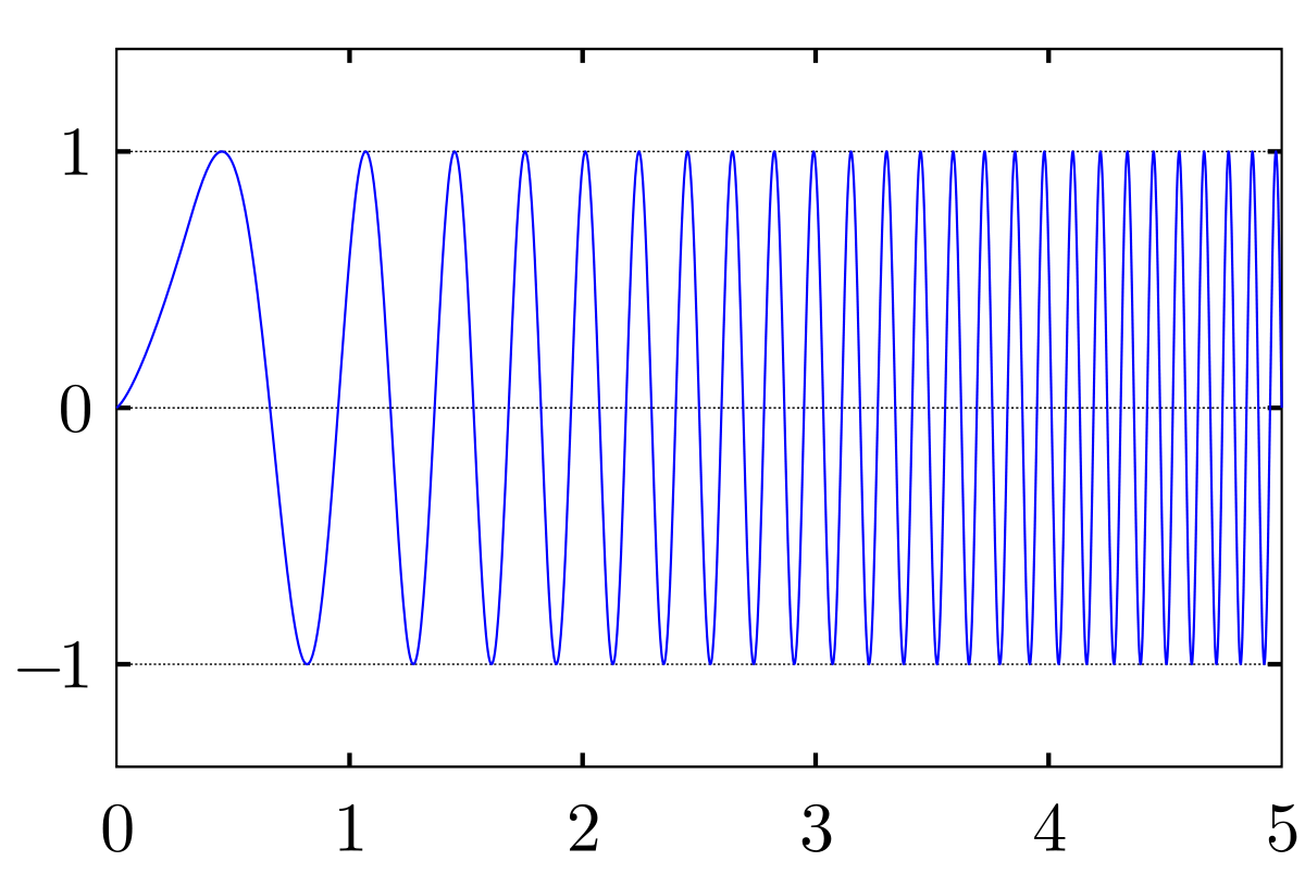
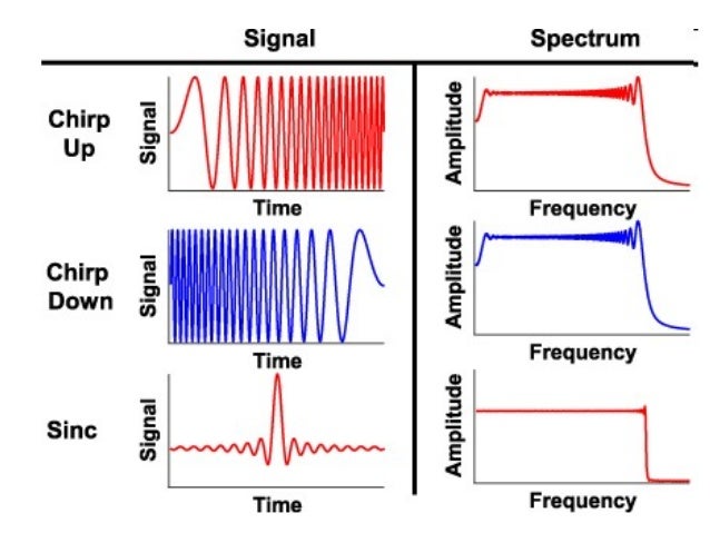
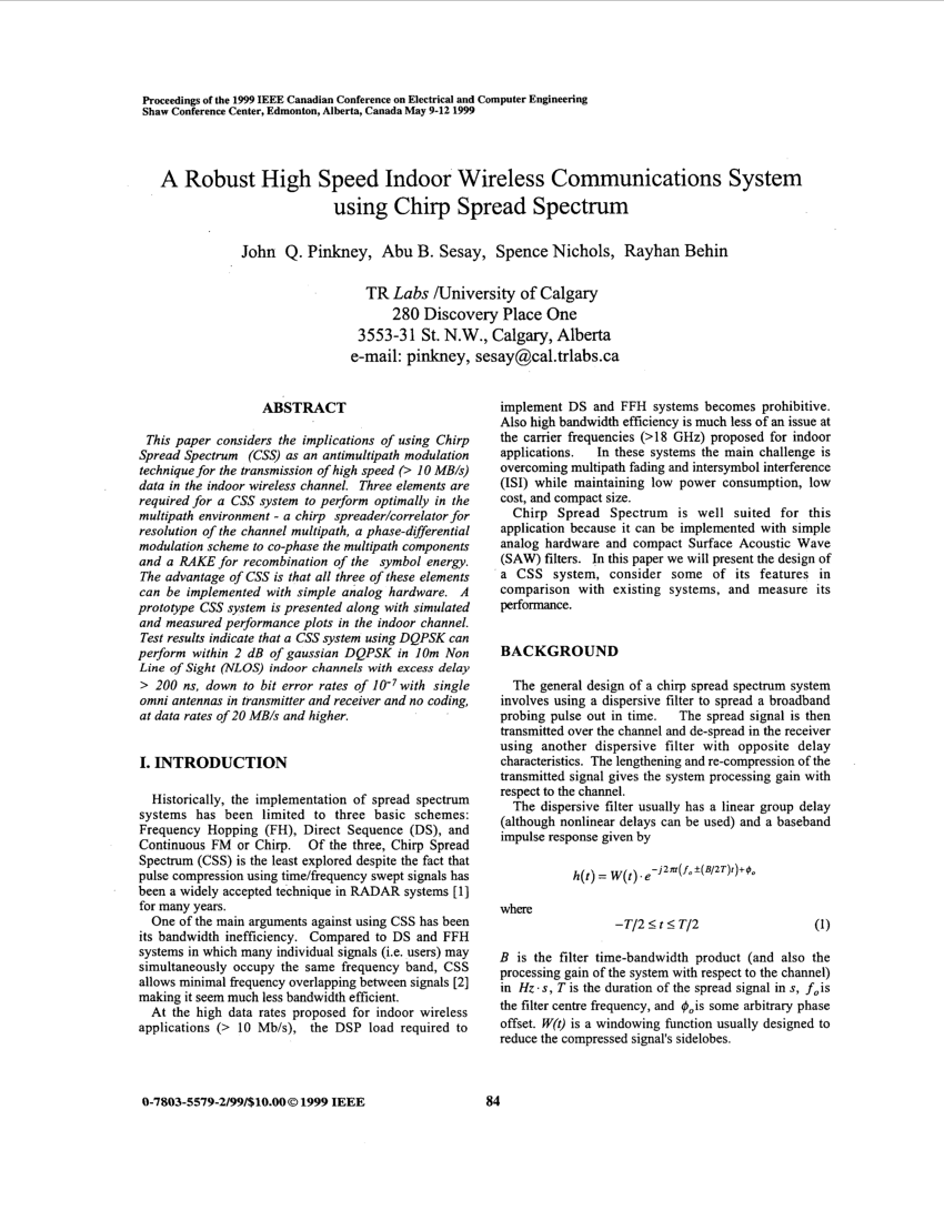
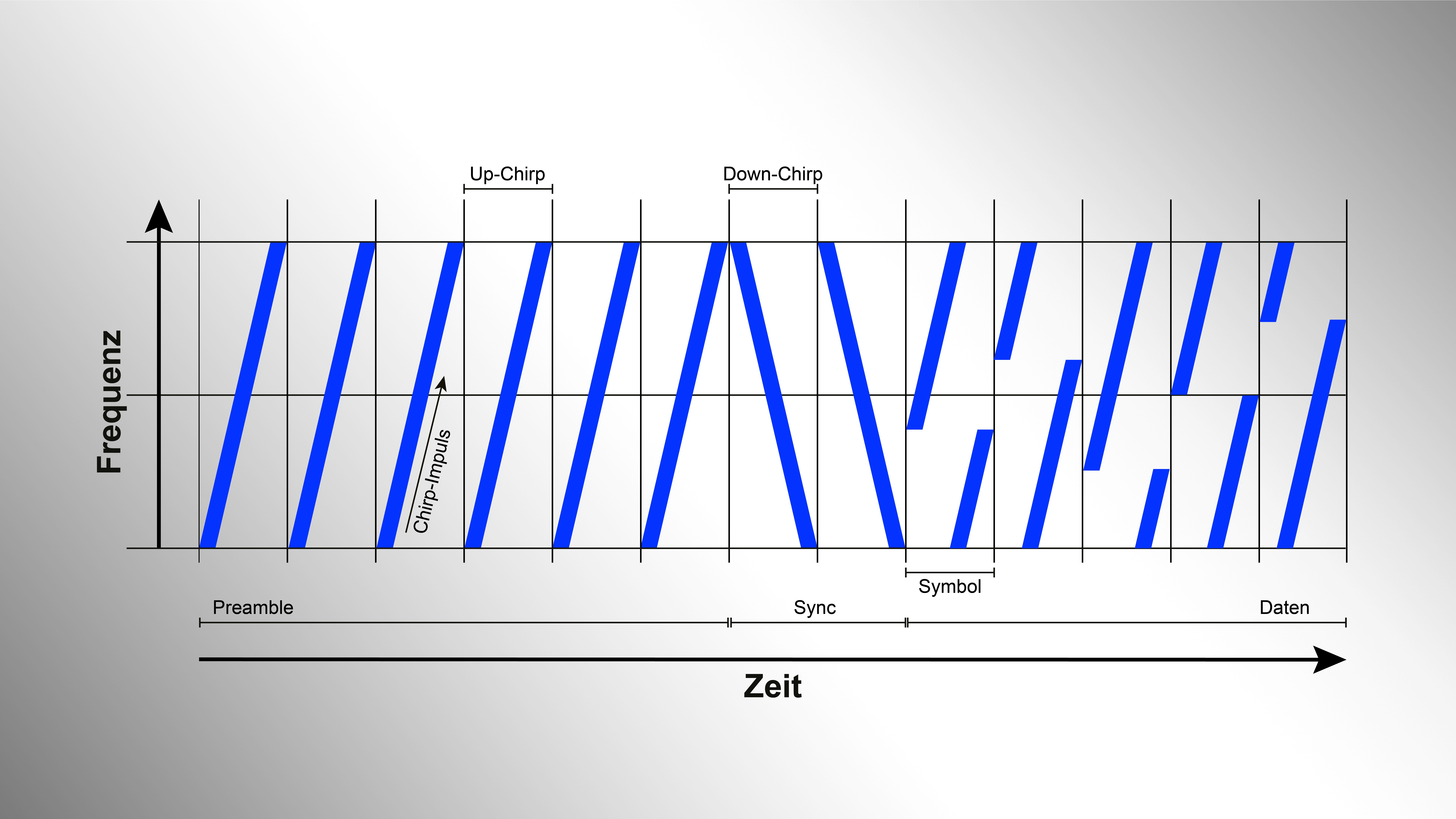
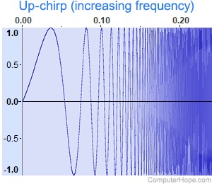
In digital communications, chirp spread spectrum ( CSS) is a spread spectrum technique that uses wideband linear frequency modulated chirp pulses to encode information. A chirp is a sinusoidal signal whose frequency increases or decreases over time (often with a polynomial expression for the relationship between time and frequency).
en.wikipedia.org/wiki/Chirp_spread_spect…
What are the two branches of Chirp Spread spectrum?
What are the two branches of Chirp Spread spectrum?
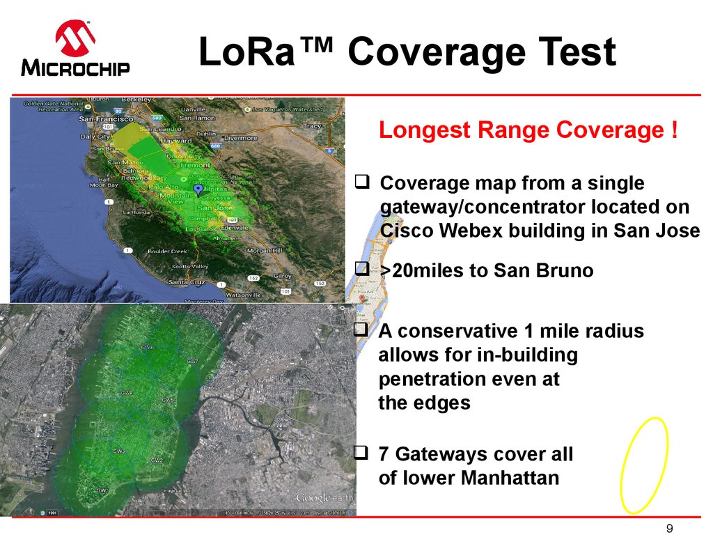
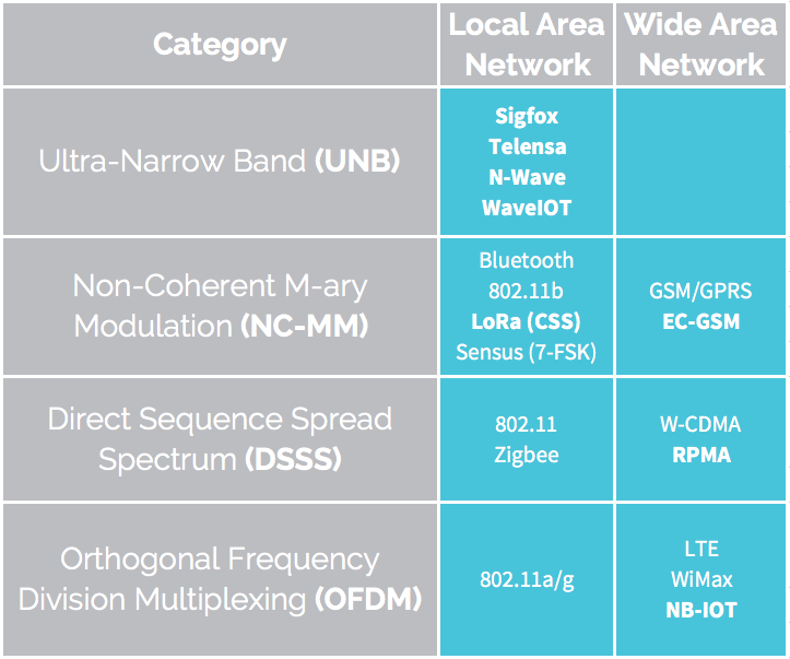
Within this family of possible technology choices, two different branches have emerged: the standards based on spreaded wideband communication and the standards based on narrowband communication, both promising to reach long range connectivity at very low power. More specifically, this paper focuses on chirp spread spectrum (CSS).
How is the spread of spectrum obtained in CSS modulation?
How is the spread of spectrum obtained in CSS modulation?
The Lora modulation is also known as CSS modulation (Chirp Spread Spectrum modulaion). In this LoRa modulation technique, spreading of spectrum is obtained by generation of a chirp signal which varies continuously in frequency. Due to this timing offset and frequency offset are equivalent between the LoRa transmitter and receiver parts.
www.rfwireless-world.com/Terminology/Lo…
When do you need a chirp signal for simulation?
When do you need a chirp signal for simulation?
Often we are confronted with the need to generate simple, standard signals ( sine, cosine , Gaussian pulse , squarewave , isolated rectangular pulse, exponential decay, chirp signal) for simulation purpose.
www.gaussianwaves.com/2014/07/chirp-s…
As with other signals, describes in the previous posts, let’s plot the FFT of the generated chirp signal and its power spectral density (PSD). Mathuranathan Viswanathan, is an author @ gaussianwaves.com that has garnered worldwide readership.
www.gaussianwaves.com/2014/07/chirp-s…
https://en.m.wikipedia.org/wiki/Chirp_spread_spectrum
Ориентировочное время чтения: 3 мин
In digital communications, chirp spread spectrum (CSS) is a spread spectrum technique that uses wideband linear frequency modulated chirp pulses to encode information. A chirp is a sinusoidal signal whose frequency increases or decreases over time (often with a polynomial expression for the relationship between time and frequency).
https://m.youtube.com/watch?v=CfBWgPpTQIo
03.05.2017 · chirp spread spectrum meaning - chirp spread spe... http://www.theaudiopedia.com What is CHIRP SPREAD SPECTRUM? What does CHIRP SPREAD SPECTRUM …
LoRa/LoRaWAN tutorial 12: Modulation Types and Chirp Spread Spectrum
Chirp Spread Spectrum Transmission using Software Defined Radios (SDR) in MATLAB App Designer
What is CHIRP SPREAD SPECTRUM? What does CHIRP SPREAD SPECTRUM mean? CHIRP SPREAD SPECTRUM meaning
Wireless Sensor Networks (WSN)-9: DSSS, FHSS, and Chirp Spread Spectrum
YouTube › Mustafa Sadiq ICT Academy
Spread Spectrum Clock Analysis with RF vs Time Triggering
https://ieeexplore.ieee.org/document/7797659
22.11.2016 · Chirp spread spectrum as a modulation technique for long range communication. Abstract: Long range low power is a family of technologies promising to connect thousands of sensors to the future internet of things. Within this family of possible technology choices, two different branches have emerged: the standards based on spreaded …
https://www.ozon.ru/product/chirp-spread-spectrum-31808585
В наличии Книга "Chirp Spread Spectrum", LAP Lambert Academic Publishing в интернет-магазине OZON со скидкой! Отзывы и фото 🚚 Быстрая доставка по …
https://ru.abcdef.wiki/wiki/Chirp_spread_spectrum
Спектр распространения щебета - Chirp spread spectrum Из Википедии, бесплатной энциклопедии Линейная частотно-модулированная повышающая частота …
https://en.m.wikipedia.org/wiki/Chirp_spectrum
Ориентировочное время чтения: 8 мин
There is very little spectral content beyond the sweep frequency range of a chirp pulse and this is especially true for waveforms where the time-bandwidth product is large. The full line on the graph of the adjacent figure shows results for linear chirps. It shows, for example, that only about 2% of the total power resides at frequencies outside the sweep range ΔF when the time-bandwidth is 100, and it is less than 1/2% when T.ΔF is 500. In the case of a non-l…
There is very little spectral content beyond the sweep frequency range of a chirp pulse and this is especially true for waveforms where the time-bandwidth product is large. The full line on the graph of the adjacent figure shows results for linear chirps. It shows, for example, that only about 2% of the total power resides at frequencies outside the sweep range ΔF when the time-bandwidth is 100, and it is less than 1/2% when T.ΔF is 500. In the case of a non-linear chirp, or a linear chirp shaped by amplitude weighting, the fraction of power outside ΔF is even lower, as is shown on the graph, where the dashed line is for spectra with Hamming profiles. This low spectral spread is particularly significant when baseband signals are to be digitized since it permits a sampling frequency to be chosen which is only slightly higher than twice the maximum frequency excursion of the chirp.
Reducing Spectral Ripple
The Fresnel ripples on a chirp spectrum are very obtrusive, especially when time-bandwidth products are low (under 50, say) and their presence leads to high time sidelobe levels when chirps are subject to pulse compression as in radar and sonar systems. They arise because of the sudden discontinuities in the chirp waveform at the commencement and termination of the pulse. Although there are a number of procedures that can be applied to reduce the ripple levels, they are not all equally effective. Furthermore, some of the methods require amplitude shaping, or amplitude modulation, of the chirp pulse and this makes those methods unsuitable when, for example, the chirp pulses are to be transmitted by a power amplifier operating in a near-limiting condition. For such systems only the methods using frequency (or phase) pre-distortion are appropriate.
Introducing Rise and Fall Times of Finite Duration
If the transitions at the start and end of the chirp are made less sudden (or more 'rounded'), then a reduction in ripple amplitude is achieved. The durations of the two transition regions need only be a small fraction of the pulse duration, and suggested values are between 2/ΔF and 3/ΔF but, as expected, when the time-bandwidth product of the pulse is small, longer transition periods are needed. The actual profiles of these rise and fall regions of a pulse do not seem to be critical and may be provided, for example, by band limiting filters in analogue implementations and a linear slope in digital ones. Two examples show the spectra of linear chirps with finite rise-times. The first is for a chirp with time-bandwidth of 250, where the rise and fall times are 4% of the total pulse duration and the second is for a chirp with time-bandwidth of 25, where the rise and fall times are 10% of the total. These two spectra show a marked reduction in ripple amplitude compared to the spectra of unmodified linear chirps shown earlier.
Applying Phase or Frequency Distortion to the Chirp Pulse
A analogous technique can be applied to the frequency characteristic of the chirp waveform by adding linear FM distortion segments (quadratic phase modulation distortion) to the frequency characteristic of the chirp, as shown. The method is effective because amplitude and phase distortions having functional similarity can produce similar effects when the distortion factors are small.
Suggested values for these distortion regions, to give good results are:
Later work proposed slightly different values, namely: but the outcome can doubtless be improved by optimizing values for each particular situation. Two plots show the effects of frequency pre-correction and can be compared to the results in the earlier sections.
The ripple reduction achieved by frequency pre-correction, although significant, is seen to be less successful than that achieved by the amplitude modulation methods of the previous section. However, it has been suggested that by implementing cubic (rather than quadratic) phase pre-correction, comparable results can be achieved.
Deriving a Waveform from a Target Frequency Spectrum
This method uses an inverse Fourier transform in order to derive a waveform which has a spectrum with the phase characteristic of a chosen chirp but a new amplitude profile which is rectangular and ripple free. The method is very effective but, unfortunately, the waveform that is so derived has a semi-infinite time duration. If, for convenience, the newly derived waveform is truncated to a practical length, then some ripple is reintroduced onto the spectrum. As an example, a linear chirp waveform with a time bandwidth of 25 is shown together with its spectrum magnitude (shown by a full line) which, as demonstrated earlier, has a large ripple component. It is possible to find, by means of an inverse FFT, a chirp waveform which, in the frequency domain, has the same phase characteristic as before, but with the rectangular magnitude characteristic shown by the dashed line on the plot. The chirp waveform resulting from this process has a very long time duration, but when it is truncated to say, a length 2T, then the spectrum acquires some ripple once more, as shown.
Applying Window Functions
There are many applications in which a spectrum with a rectangular magnitude profile is not ideal. For example, when a chirp waveform is compressed by means of its matched filter, then the resultant waveform approximates to the sinc function and, consequently, has annoyingly high sidelobes. Often, to improve the characteristics of the pulse and lower the sidelobe levels, its spectrum is modified, typically to a bell-shaped profile. Similar problems arise in digital signal processing where the spectral shaping is provided by a window function, a process sometimes called apodization. In the case of an antenna array, similar profiling by "weighting functions" is used to reduce the spatial sidelobes of the radiation pattern. Although spectral shaping of a chirp could be applied in the frequency domain, better results are obtained if the shaping is carried out in the time domain. Examples of this process are shown for linear chirps with time-bandwidth products of 250 and 25. They have been shaped by a 3-term Blackman-Harris window given by The spectra, now bell-shaped, are seen to be free of ripples.
Non-linear chirps can be devised that have a bell shaped spectrum, such as the Blackman-Harris window just discussed, and consequently will exhibit reduced ripple compared to the linear chirp. By means of the stationary phase method described earlier, an approximate relationship between time and frequency can be obtained and is:
Rearranging the equation, a plot of frequency against time can be plotted, as shown.
As examples, plots of the spectral magnitudes of non-linear chirps with spectral profiles of Blackman-Harris windows and with time-bandwidth products of 250 and 25 are shown below. As can be seen, there is some ripple reduction, but the disappointing performance can be attributed to the fact that these chirps, although they have reduced energy content in their outer frequency regions, they still have amplitude profiles with fast rise and fall times.
https://www.gaussianwaves.com/2014/07/chirp-signal-frequency-sweeping-fft-and-power...
25.07.2014 · Chirp signals/signatures are encountered in many applications ranging from radar, sonar, spread spectrum, optical communication, image processing, doppler effect, motion of a pendulum, as gravitation waves, manifestation as Frequency Modulation (FM), echo location etc.
https://www.rfwireless-world.com/Terminology/LoRa-modulation-vs-CSS-modulation.html
In this LoRa modulation technique, spreading of spectrum is obtained by generation of a chirp signal which varies continuously in frequency. Due to this timing offset and …
Рекламаchirp - подберите по цене и купите выгодно!
Не удается получить доступ к вашему текущему расположению. Для получения лучших результатов предоставьте Bing доступ к данным о расположении или введите расположение.
Не удается получить доступ к расположению вашего устройства. Для получения лучших результатов введите расположение.
In digital communications, chirp spread spectrum (CSS) is a spread spectrum technique that uses wideband linear frequency modulated chirp pulses to encode information.[1] A chirp is a sinusoidal signal whose frequency increases or decreases over time (often with a polynomial expression for the relationship between time and frequency).
As with other spread spectrum methods, chirp spread spectrum uses its entire allocated bandwidth to broadcast a signal, making it robust to channel noise. Further, because the chirps utilize a broad band of the spectrum, chirp spread spectrum is also resistant to multi-path fading even when operating at very low power. However, it is unlike direct-sequence spread spectrum (DSSS) or frequency-hopping spread spectrum (FHSS) in that it does not add any pseudo-random elements to the signal to help distinguish it from noise on the channel, instead relying on the linear nature of the chirp pulse. Additionally, chirp spread spectrum is resistant to the Doppler effect, which is typical in mobile radio applications.[2]
Chirp spread spectrum was originally designed to compete with ultra-wideband for precision ranging and low-rate wireless networks in the 2.45 GHz band. However, since the release of IEEE 802.15.4a (also known as IEEE 802.15.4a-2007), it is no longer actively being considered by the IEEE for standardization in the area of precision ranging.
Chirp spread spectrum is ideal for applications requiring low power usage and needing relatively low data rates (1 Mbit/s or less). In particular, IEEE 802.15.4a specifies CSS as a technique for use in low-rate wireless personal area networks (LR-WPAN). However, whereas IEEE 802.15.4-2006 standard specifies that WPANs encompass an area of 10 m or less, IEEE 802.15.4a-2007, specifies CSS as a physical layer to be used when longer ranges and devices moving at high speeds are part of your network. Nanotron's CSS implementation was actually seen to work at a range of 570 meters between devices.[3] Further, Nanotron's implementation can work at data rates of up to 2 Mbit/s - higher than specified in 802.15.4a.[4] Finally, the IEEE 802.15.4a PHY standard actually mixes CSS encoding techniques with differential phase shift keying modulation (DPSK) to achieve better data rates.
Chirp spread spectrum may also be used in the future for military applications as it is very difficult to detect and intercept when operating at low power.[5]
Very similar frequency swept waveforms are used in frequency modulated continuous wave radars to measure range (distance); an unmodulated continuous wave Doppler radar can only measure range-rate (relative velocity along the line of sight). FM-CW radars are very widely used as radio altimeters in aircraft.
Content is available under CC BY-SA 3.0 unless otherwise noted.
Private Love Diego Power Remix
Little Top Young Pedosex
Film Taboo Part 1 And 2
Webcam Ohmibod Squirt
What Are Some Lesbian Dating Apps
Chirp spread spectrum - Wikipedia
Chirp spread spectrum as a modulation technique for long ...
Книга "Chirp Spread Spectrum" – купить книгу ISBN ...
Расширенный спектр щебета - Chirp spread spectrum - abcdef ...
Chirp spectrum - Wikipedia
LoRa Modulation Basics | CSS Modulation | Advantages ...
Chirp Spread Spectrum


.png)