Cathode Ray Tube

💣 👉🏻👉🏻👉🏻 ALL INFORMATION CLICK HERE 👈🏻👈🏻👈🏻
https://en.m.wikipedia.org/wiki/Cathode-ray_tube
Ориентировочное время чтения: 8 мин
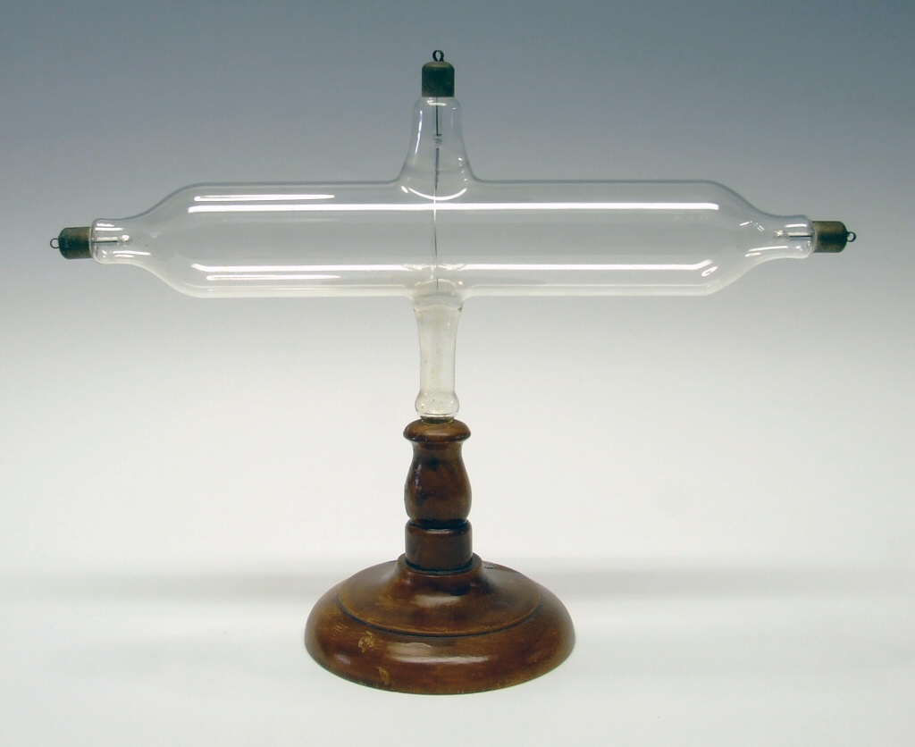
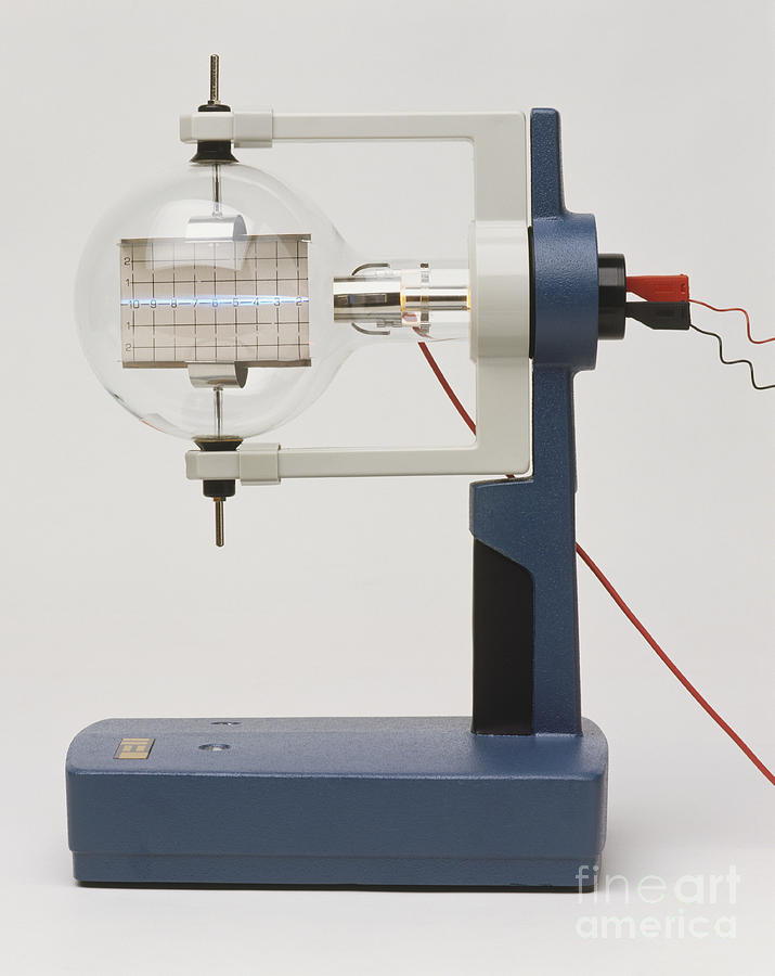
A cathode-ray tube (CRT) is a vacuum tube containing one or more electron guns, the beams of which are manipulated to display images on a phosphorescent screen. The images may represent electrical waveforms (oscilloscope), pictures (television set, computer monitor), radar targets, or other phenomena. A CRT on a television set is commonly called a picture tube. CRTs have also been used as memory devices, in which case the screen is not intended to be visib…
A cathode-ray tube (CRT) is a vacuum tube containing one or more electron guns, the beams of which are manipulated to display images on a phosphorescent screen. The images may represent electrical waveforms (oscilloscope), pictures (television set, computer monitor), radar targets, or other phenomena. A CRT on a television set is commonly called a picture tube. CRTs have also been used as memory devices, in which case the screen is not intended to be visible to an observer.
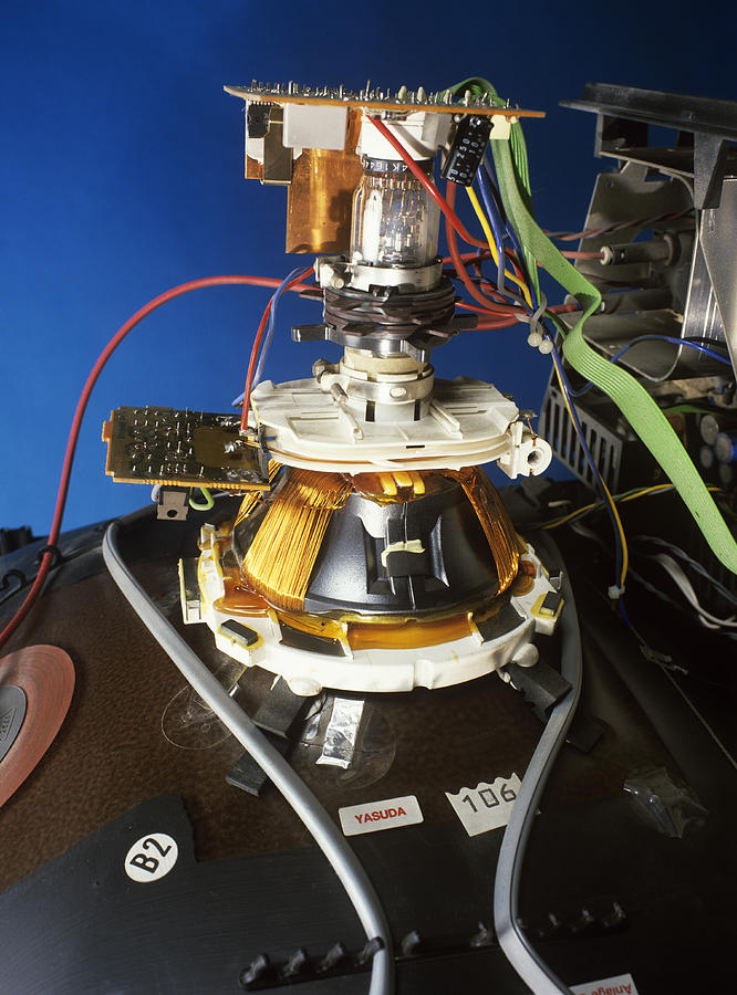
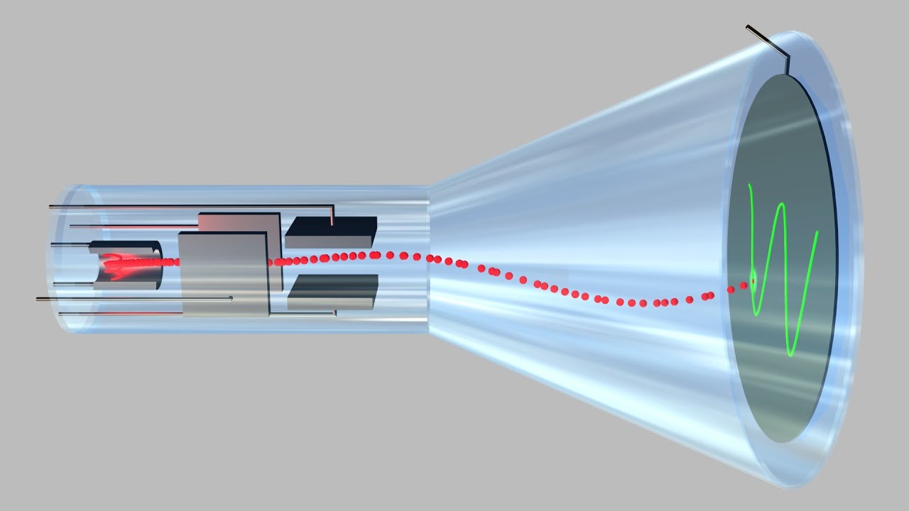
In television sets and computer monitors, the entire front area of the tube is scanned repeatedly and systematically in a fixed pattern called a raster. In color devices, an image is produced by controlling the intensity of each of three electron beams, one for each additive primary color (red, green, and blue) with a video signal as a reference. In modern CRT monitors and televisions the beams are bent by magnetic deflection, using a deflection yoke. Electrostatic deflection is commonly used in oscilloscopes.
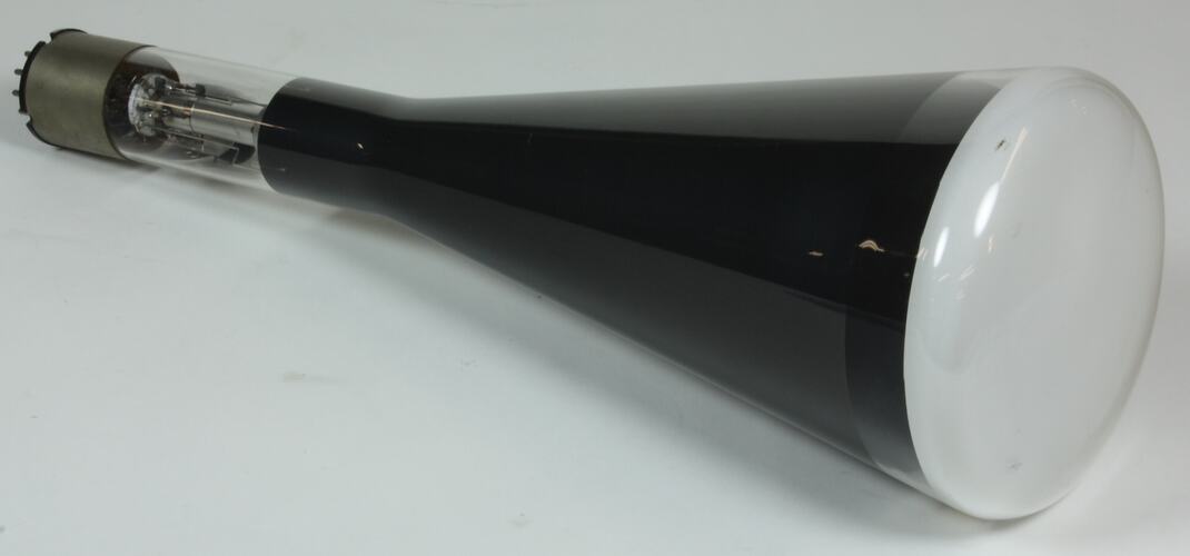
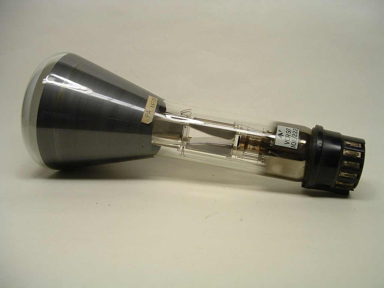
A CRT is a glass envelope which is deep (i.e., long from front screen face to rear end), heavy, and fragile. The interior is evacuated to approximately 0.01 pascals (9.9×10 atm) to 133 nanopascals (1.31×10 atm), to facilitate the free flight of electrons from the gun(s) to the tube's face without scattering due to collisions with air molecules. As such, handling a CRT carries the risk of violent implosion that can hurl glass at great velocity. The face is typically made of thick lead glass or special barium-strontium glass to be shatter-resistant and to block most X-ray emissions. CRTs make up most of the weight of CRT TVs and computer monitors.
Since the Early 2010s, CRTs have been superseded by flat-panel display technologies such as LCD, plasma display, and OLED displays which are cheaper to manufacture and run, as well as significantly lighter and less bulky. Flat-panel displays can also be made in very large sizes whereas 40 in (100 cm) to 45 in (110 cm) was about the largest size of a CRT.
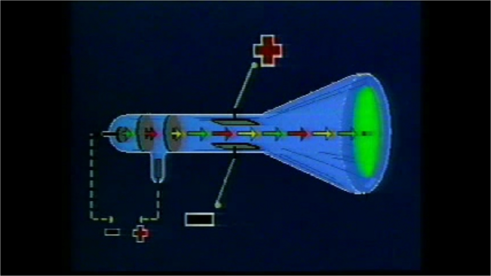
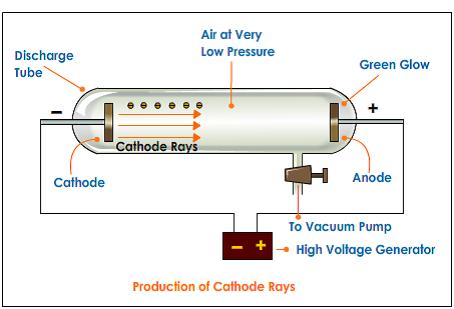
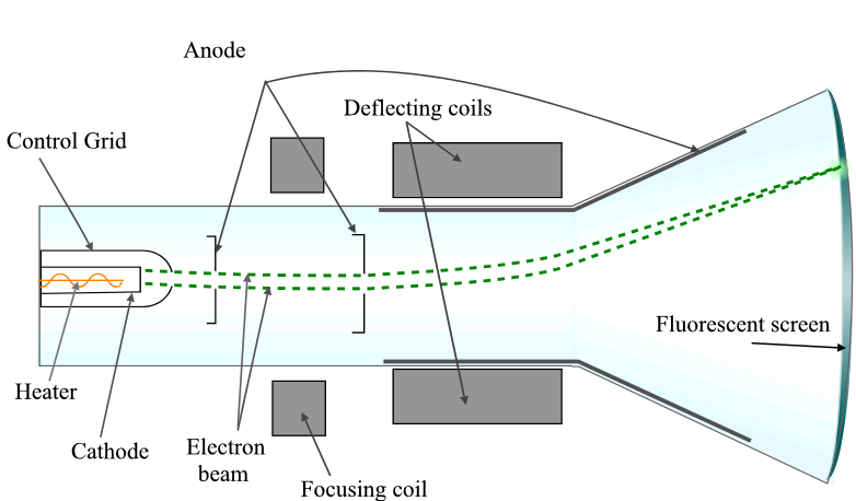
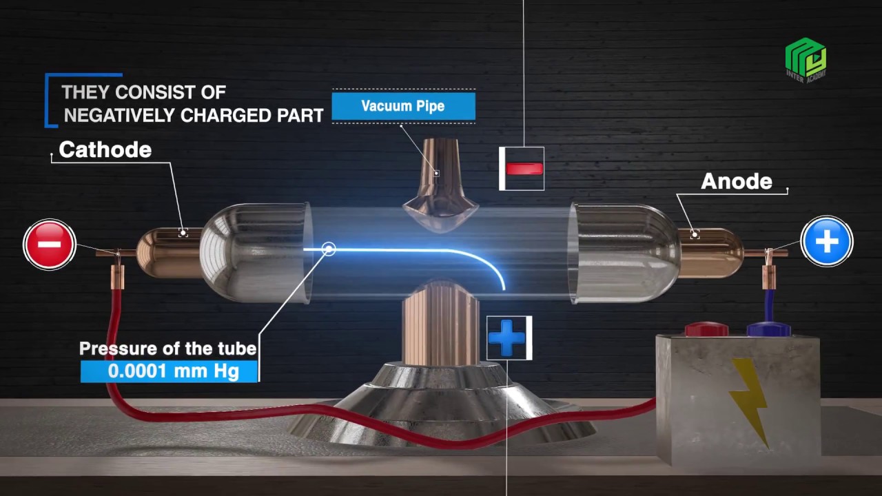
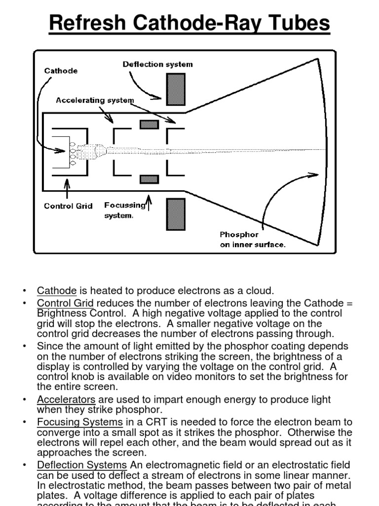
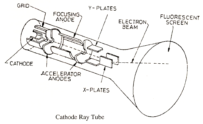
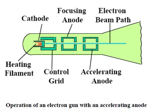
A CRT works by electrically heating a tungsten coil which in turn heats a cathode in the rear of the CRT, causing it to emit electrons which are modulated and focused by electrodes. The electrons are steered by deflection coils or plates, and an anode accelerates them towards the phosphor-coated screen, which generates light when hit by the electrons.
Before the invention of the integrated circuit, CRTs were thought of as the most complicated consumer electronics product.
https://chemdemos.uoregon.edu/demos/Cathode-Ray-Tubes
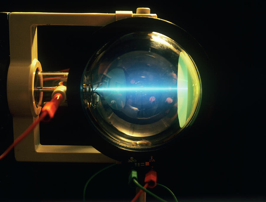
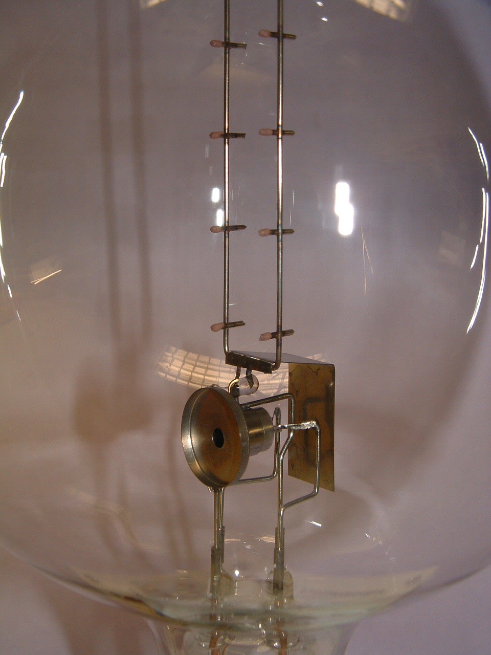
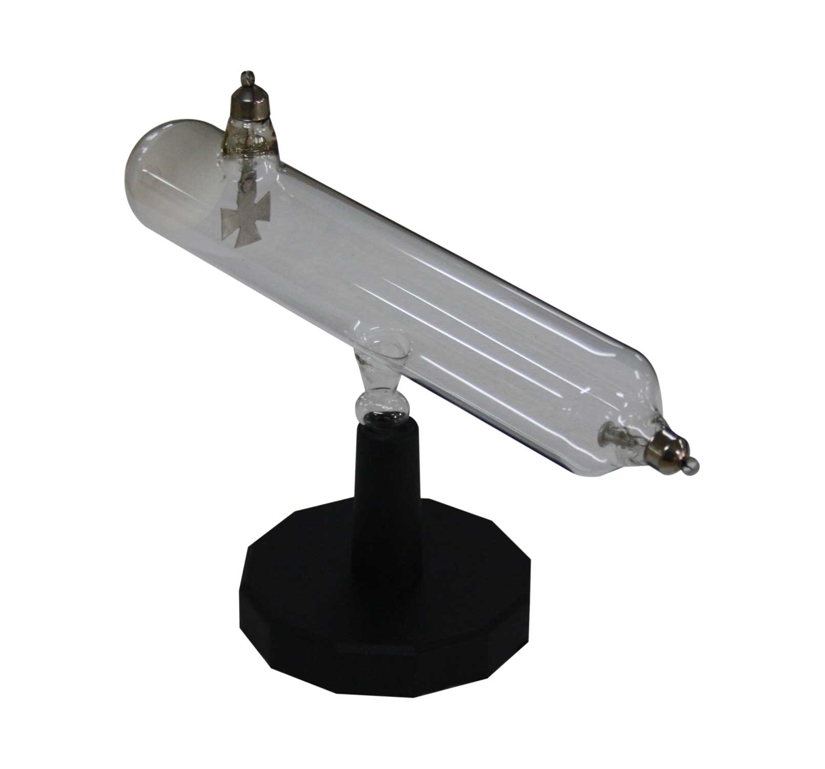
Cathode Ray Tube #16 - light shined on a pinwheel inside a CRT does not cause the pinwheel to move. However, when cathode rays strike the pinwheel inside the CRT, the pinwheel begins to spin and move. Cathode Ray Tube # 18 - in a darkened room, the electron beam (cathode rays…
https://www.sciencedirect.com/topics/engineering/cathode-ray-tube
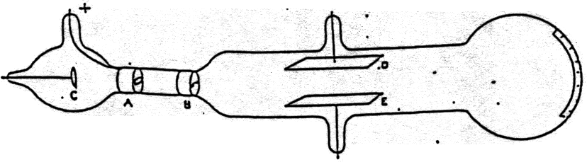
THE CATHODE RAY TUBE. The principle of the cathode ray tube (CRT) is illustrated in Fig. 15.20. A hot cathode produces an electron beam which passes through two deflecting devices, one of …
https://en.m.wikipedia.org/wiki/Direct-view_television
Ориентировочное время чтения: 9 мин
The cathode-ray tube (CRT) is a vacuum tube that contains one or more electron guns and a phosphorescent screen, and is used to display images. It modulates, accelerates, and deflects electron beam(s) onto the screen to create the images. The images may represent electrical waveforms (oscilloscope), pictures (television, computer monitor), radar targets, or other phenomena. CRTs have also been used as memory devices, in which case the visible light emitted fr…
The cathode-ray tube (CRT) is a vacuum tube that contains one or more electron guns and a phosphorescent screen, and is used to display images. It modulates, accelerates, and deflects electron beam(s) onto the screen to create the images. The images may represent electrical waveforms (oscilloscope), pictures (television, computer monitor), radar targets, or other phenomena. CRTs have also been used as memory devices, in which case the visible light emitted from the fluorescent material (if any) is not intended to have significant meaning to a visual observer (though the visible pattern on the tube face may cryptically represent the stored data).
In television sets and computer monitors, the entire front area of the tube is scanned repetitively and systematically in a fixed pattern called a raster. In color devices, an image is produced by controlling the intensity of each of the three electron beams, one for each additive primary color (red, green, and blue) with a video signal as a reference. In all modern CRT monitors and televisions, the beams are bent by magnetic deflection, a varying magnetic field generated by coils and driven by electronic circuits around the neck of the tube, although electrostatic deflection is commonly used in oscilloscopes, a type of electronic test instrument.
A CRT is constructed from a glass envelope which is large, deep (i.e., long from front screen face to rear end), fairly heavy, and relatively fragile. The interior of a CRT is evacuated to approximately 0.01 pascals (9.9×10 atm) to 133 nanopascals (1.31×10 atm), evacuation being necessary to facilitate the free flight of electrons from the gun(s) to the tube's face. The fact that it is evacuated makes handling an intact CRT potentially dangerous due to the risk of breaking the tube and causing a violent implosion that can hurl shards of glass at great velocity. As a matter of safety, the face is typically made of thick lead glass so as to be highly shatter-resistant and to block most X-ray emissions, particularly if the CRT is used in a consumer product.
Since the late 2000s, CRTs have been largely superseded by newer "flat panel" display technologies such as LCD, plasma display, and OLED displays, which have lower manufacturing costs and power consumption, as well as significantly less weight and bulk. Flat-panel displays can also be made in very large sizes; whereas 38 to 40 in (97 to 102 cm) was about the largest size of a CRT television, flat panels are available in 85 in (220 cm) and even larger sizes.
Cathode Ray Tube - How It Works ? Easy Explanation . Engineering - Physics
Cathode Ray Tube Experiment and Charge To Mass Ratio of an Electron
YouTube › The Organic Chemistry Tutor
DIY Cathode Ray Tube: Interacting With Electrons
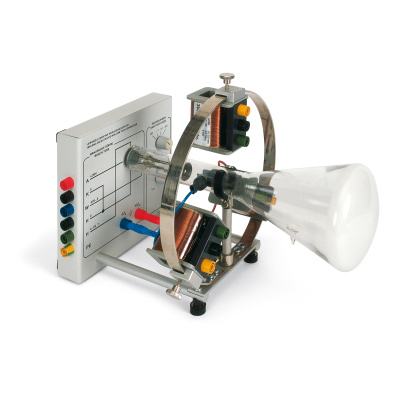
Cathode Ray Tube (Electron Accelerator)
https://www.britannica.com/technology/cathode-ray-tube
25.08.2021 · Cathode-ray tube (CRT), Vacuum tube that produces images when its phosphorescent surface is struck by electron beams. CRTs can be monochrome (using one …
https://m.youtube.com/watch?v=7YHwMWcxeX8
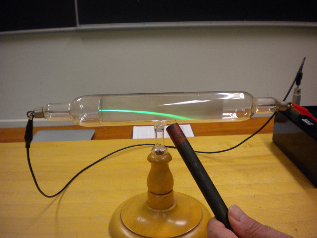
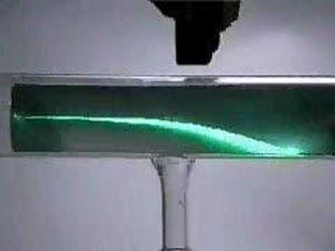
19.02.2008 · The path of the electron beam is curved in a magnetic field.
What are the images in a cathode ray tube?
What are the images in a cathode ray tube?
A cathode-ray tube ( CRT) is a vacuum tube containing one or more electron guns, the beams of which are manipulated to display images on a phosphorescent screen. The images may represent electrical waveforms ( oscilloscope ), pictures ( television set, computer monitor ), radar targets, or other phenomena.
en.m.wikipedia.org/wiki/Cathode-ray_tube
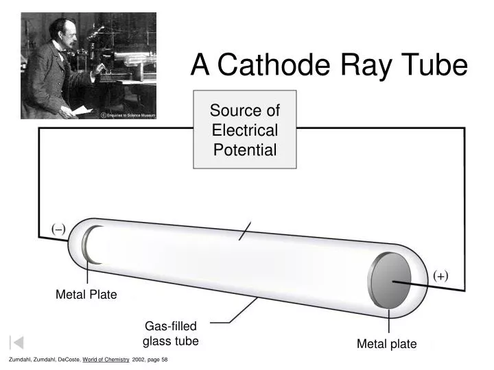
Where does the negative lead go in a cathode ray tube?
Where does the negative lead go in a cathode ray tube?
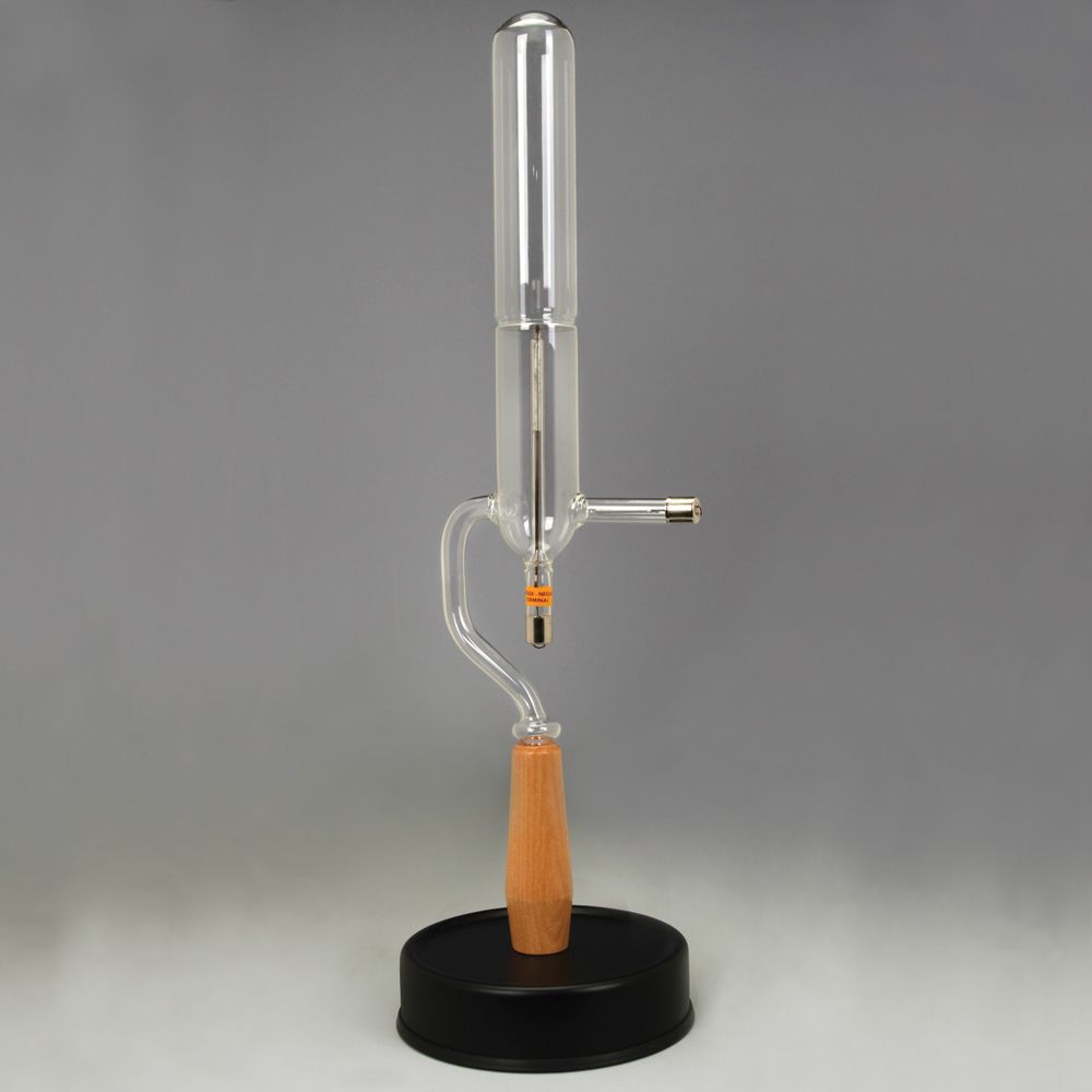
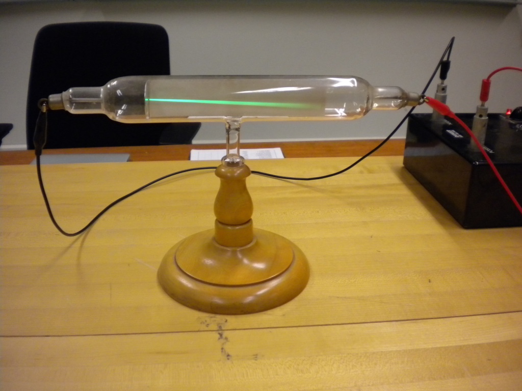
The negative lead goes in the jack in the center of the back of the electron gun part of the CRT. The positive lead goes in the jack on the side of the electron gun part of the CRT. Connect the leads from the 120 VAC output of the high voltage DC/ 120 VAC power supply to the CRT.
chemdemos.uoregon.edu/demos/Cathode-R…
How does the electron move in a cathode ray tube?
How does the electron move in a cathode ray tube?
The one pair of plate moves the beam upward and the second pair of plate moves the beam from one side to another. The horizontal and vertical movement of the electron are independent of each other, and hence the electron beam positioned anywhere on the screen.
circuitglobe.com/cathode-ray-tube-crt.html
How do you deflect a cathode ray tube?
How do you deflect a cathode ray tube?
The trace of a cathode ray should appear on the phosphorescent screen. Turn up the power on the high voltage source connected to the capacitor plates. The cathode ray should be deflected upward. Turn down both power supplies all the way. If desired, switch the leads going to the deflection plates and repeat the process.
chemdemos.uoregon.edu/demos/Cathode-R…
https://circuitglobe.com/cathode-ray-tube-crt.html
06.06.2017 · Cathode Ray Tube (CRT) Definition: The CRT is a display screen which produces images in the form of the video signal. It is a type of vacuum tube …
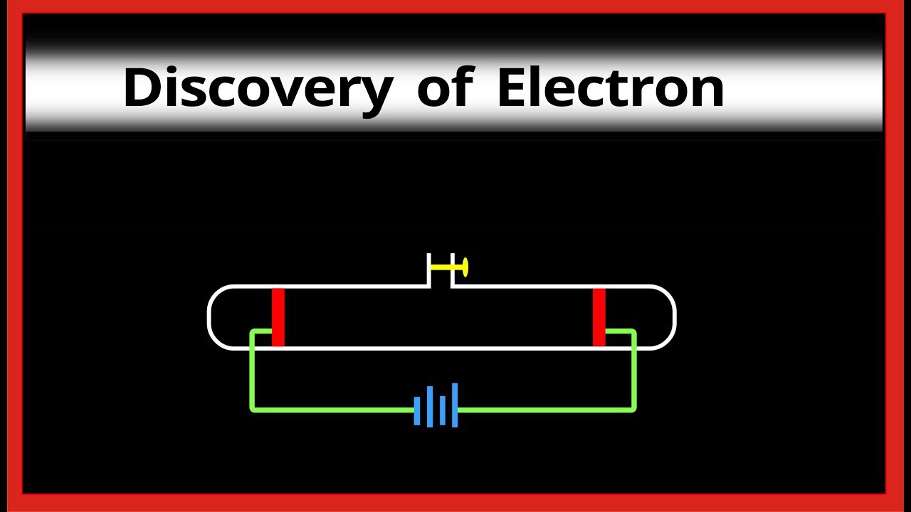
https://m.youtube.com/watch?v=vXOeehVTcRA
22.02.2018 · This video demonstrate the concept of Discovery of Electron and its properties by using cathode ray tube…
Не удается получить доступ к вашему текущему расположению. Для получения лучших результатов предоставьте Bing доступ к данным о расположении или введите расположение.
Не удается получить доступ к расположению вашего устройства. Для получения лучших результатов введите расположение.
A CRT converts electrical signals to the visual display seen on the screen, using an electron gun to emit a beam of electrons and project them onto a screen.
CRT/LCD Most graphics displays are based on the cathode ray tube (CRT). A CRT contains an electron beam which is focused onto a phosphor-coated glass screen when light is emitted. High-quality CRTs allow the spot to be focused down to a very small area which improves the resolution of the device. The resolution is the maximum number of points which can be displayed per centimetre in the horizontal or vertical directions. The electron beam must be deflected in order to draw points anywhere on the whole screen surface. For high-resolution systems this requires a fast scan rate and complex deflection systems in order to maintain a linear display, and the video monitor is an expensive item in such systems. The electron beam may be modulated in intensity to give a range of grey tones in a monochrome system or to offer a range of hues in a colour system. The maximum rate of modulation determines the detail which can be displayed in the image and is the video bandwidth of the monitor.*
Most displays are now full colour where the screen is coated with phosphor dots or stripes in red, green or blue. However, the shadow mask required in such CRTs limits the ultimate resolution to the dot pitch of the phosphor stripes. Monochrome screens are not subject to this limitation, and thus offer improved resolution where the use of colour is not essential.
Vector and raster scan The electron beam in a CRT may be deflected by drawing the image one line or vector at a time. Since each line could be in any direction this is known as a random-scan display. The alternative is to scan the whole area of the screen repeatedly (raster-scan) and to modulate the intensity of the beam such that an image is shown only at the desired points on the screen. While vector scan displays are capable of higher resolution, the refresh rate is dependent on the number of vectors, and this becomes a limitation where there are a large number of vectors to draw. Raster-scan displays have a fixed screen refresh rate of between 25 and 80 frames per second and this is independent of the complexity of the image.
An alternative form of display uses plasma-panel or liquid-crystal (LCD) technologies. Here, transparent electrodes are deposited onto a glass screen. By placing a voltage across the electrodes the plasma may be made to glow (plasma-panel) or the cell may become opaque (LCD). In this way, pixels may be displayed to form the image. Resolutions exceeding 1024 × 1024 are possible.
Hard copy The displays above do not give a permanent representation of the image. Hard-copy devices produce an image on paper or film.
Printers Although printers usually print text they can generally be used to produce a low-resolution image. For example, the head of a dot-matrix printer can print dots in a regular array. Since this is similar to the arrangement of an image split into individual pixels, images can be produced. However, all dots are printed with the same intensity, and so this technique is only suitable for line drawings. An attempt at shading can be produced by grouping pixels or by using dithering techniques, although at the expense of resolution. Standard dot-matrix printers can offer a graphics resolution of about 60 dots per inch (dpi) or with interpolation requiring multiple passes this may be doubled. Twenty-four-pin dot-matrix printers allow a resolution of over 200 dpi with ink-jet printers and laser printers starting at 300 dpi as standard. These are usually monochrome displays. It is possible to use colour ink-jet or laser printers to produce colour displays.
Plotters Plotters produce an image by moving a pen over the paper and constructing the image as a series of vectors. Some plotters, for convenience, move the pen across the paper width (in one direction) and then move the paper itself under the pen in the orthogonal direction in order to draw the vectors. In this way, very large plots can be drawn. A plotter does not have to use ink; photoplotters use light-pens of varying widths which print onto photographic film contained in a light-proof box. This allows photographic masters (either negative or positive) to be produced. This technique is often used in the production of printed circuit board (PCB) artwork.
URL: https://www.sciencedirect.com/science/article/pii/B9780750611954500099
B. Jayant Baliga, in The IGBT Device, 2015
The CRT display requires rapid rastering of the electron beam to generate proper screen refresh rates. The horizontal deflection of the electron beam across the wider screens of larger TVs requires a high voltage (20-kV) at a frequency of 100 kHz [55]. This function is performed by using a step-up transformer as shown in Fig. 12.43. Despite a high turns ratio for the transformer, the power switch in series with the primary winding must withstand at least 900-V during each switching event. The bipolar power transistor was used for performing the switching function in the CRT deflection circuit [56] until the availability of high voltage IGBTs with reduced switching losses that were optimized for this application. With reference to bipolar junction transistors, the authors state: “Long storage times (6 to 10 ms) can pose circuit operating problems and the slow switching performance of these devices, although acceptable for operation at normal TV horizontal line scanning rates, cause thermal problems when used at higher line rates, with shorter retrace times.” Attempts to improve this situation by using complex base drive circuits add to the cost [53].
Figure 12.43. Cathode ray tube (CRT) deflection circuit using an insulated gate bipolar transistor (IGBT) driver.
Specially optimized IGBTs with high switching speed (100 kHz) and blocking voltage capability of 1500-V were developed in the early 1990s for use in CRT deflection circuits [57,58]. The current and voltage waveforms for the CRT deflection circuit are shown in Fig. 12.44. The current in the primary of the step-up transformer increases linearly with time when the IGBT is turned on. When the IGBT is turned off, its voltage increases to a peak of 1200-V due to the flyback converter operating in the resonant mode. The IGBT turnoff occurs with ZVS conditions leading to loss losses. This is important to enable operation of the IGBT has a high frequency of 100 kHz.
Figure 12.44. Cathode ray tube deflection circuit waveforms for the insulated gate bipolar transistor (IGBT).
URL: https://www.sciencedirect.com/science/article/pii/B9781455731435000122
The traditional CRT display has occupied our daily life for more than 70 years. The CRT display has the advantages of the best color reproduction, fast response, and wide view angle. However, the traditional CRT is heavy and thick, and cannot follow the requirement of modern IT development. It is hoped that a thin and light display with CRT performance can be fabricated. FED is one kind of promising technology.
Field emission is a quantum mechanics phenomenon, which was discovered in 1929 by Fowler and Nordheim (6). It can be simply described by the schematic illustration shown in Fig. 4.1.
Figure 4.1. Theory model of field emission.
Because of the applied intense electric field on the emitter surface, the barrier becomes a triangle shape and tunneling probability increases. The emission current can be described by Eq. (4.1) (7):
Here, j is the emission current density, F is the local electric field intensity, φ is the work function, t and v are the Nordheim functions (7–9), and F is the electric field above the emitter surface. For an emitter with a given geometry, the surface electric field is correlated with the macroscopic electric field E with
F=βE
. β is the electric field enhancement factor.
In the early period of FED development, Spindt-type emitters (silicon or molybdenum tips) were used as field emitters (10–12). FEDs from 6″ to 15″ diagonal have been fabricated successfully (13–15). Fabrication of the Spindt emitter is complicated and device stability is not satisfactory. The commercialized Spindt FED is still not available.
From the Fowler–Nordheim formula, we can see that the field enhancement factor will influence emission greatly. In the 1990s, with intense studies, CNTs became potential field emitters because of their large field enhancement and excellent stability (16–19). An FED with a CNT field emitter has attracted intense attention from both academia and industry (20,21). The application of a CNT emitter was first realized in an element tube (22,23). A field emission lamp has also been fabricated successfully (24,25).
To fabricate an FED, mass production of a uniform CNT emitter over a large area is a basic technical requirement. In situ chemical vapor deposition (CVD) and postformation methods such as screen printing or solution deposition are the main methods of fabricating CNT field emitters (17,18,26). Except for thermal CVD, plasma enhanced CVD has also been used to synthesize CNT emitters (27–29). Although the morphology of a CVD CNT emitter can be well controlled, the postformation method is more popular b
Crossdresser Ass Pictures
Russki Incest Doch Missax Brazzers
Russian Lesbian Anal Strapon Vk
Hentai Rape Stockings
Porn Little Lupe Riding Pov Porn
Cathode-ray tube - Wikipedia
Cathode Ray Tubes | Chemdemos
Cathode Ray Tube - an overview | ScienceDirect Topics
Cathode-ray tube - Wikipedia
Cathode-ray tube | technology | Britannica
What is Cathode Ray Tube (CRT)? - Definition, Working ...
Cathode Ray Tube