Calculation Of Kinetics Tricone Drill Bit

⚡ 👉🏻👉🏻👉🏻 ИНФОРМАЦИЯ ДОСТУПНА ЗДЕСЬ ЖМИТЕ 👈🏻👈🏻👈🏻
Figure 1 : IADC TriCone Drill Bit Dull Grading
Figure 2 : IADC TriCone Drill Bit Dull Grading
Table 1 : Cutting Structure Location (L) Of IADC Tricone Bit Dull Grading
Figure 3 : IADC TriCone Drill Bit Dull Grading The Two Thirds Rule
Figure 4 : IADC TriCone Drill Bit Dull Grading – bit dull characteristic
Figure 5 : IADC TriCone Drill Bit Dull Grading – Reason for POOH
Figure 7 : Cutters Wear In PDC Bit Dull Grading
Figure 8 : Dull Characteristics In PDC Bit Dull Grading
Figure 9 : Stud Cutter Wear Characteristics In PDC Bit Dull Grading
Figure 10 : Cylinder Cutters Wear Characteristics In PDC Bit Dull Grading
Drilling Manual | All Rights Reserved 2020
Our goal to provide assistance to build your knowledge about drilling oilfield. The contents are presented in easy way in order to make learning from this website an easy job.
As each drill bit is pulled from the hole its physical appearance is inspected and graded according to the wear it has sustained and this is called Bit Dull Grading . In this article, we will explain why we need to do IADC Bit Dull Grading For Both PDC Drill Bit & TriCone Drill Bit.
Please subscribe with your e-mail to get latest educational articles and job vacancies
The IADC Bit Dull Grading system has recently been revised (1987) so that it may be applied to all types of bit ( Tricone or fixed cutter ( PDC , Diamond) ). The system is based on the chart and will be described in terms of each column:
The evaluation of bits is useful for the following reasons:
A bit record will always be kept by the operating company, drilling contractor and/or bit vendor. This bit record is used to store the following information about the bit after it has completed its run:
In the first column of IADC TriCone bit dull grading, we usually report the condition of the cutting structure on the inner 2/3 rds of the bit which is not touching the wall of the hole (Inner)
In the second column of Tricone IADC bit dull grading, we usually report the condition of the cutting structure on the outer 1/3 rd of the bit for Tricone bits.
In column 1 and 2 a linear scale from 0 to 8 is used to describe the condition of the cutting structure as follows
Steel Tooth Bits : a measure of the lost tooth height.
Insert Bits : a measure of total cutting structure reduction due to lost, worn and/or broken inserts
The tooth wear of insert bits is a measure of the combined cutting structure reduction due to lost, worn and broken inserts. For example,
Report the major dull characteristics of the bit cutting structure based on the below (check Major 24 Tricone Bit Dull Grading Characteristics ) :
Cone numbers are identified as follows:
Report the location on the face of the bit where the major cutting structure dulling characteristic occurs. This may be reported in the form of a letter or number code The location of dull characteristics for four fixed bit profiles is shown in below table
Cone numbers are identified as follows:
For Fixed Cutter we can use the following:
C — Cone N — Nose T — Taper S — Shoulder G — Gauge A — All Areas
Report the bearing condition of roller cone bits. The grading will depend on the type of bit. This space will always be occupied by an ‘X’ for fixed cutter bits.
Report on the gauge of the bit. The letter “I” is used if the bit has no gauge reduction. If the bit does have a reduction in gage it is to be recorded in 1/16th of an inch.
The Two Thirds Rule, as used for three-cone bits, requires that the gage ring be pulled so that it contacts two of the cones at their outermost points. Then the distance between the outermost point of the third cone and the gage ring is multiplied by 2/3’s and rounded to the nearest 1/16th of an inch to give the correct diameter reduction.
Report any dulling characteristic of the bit in addition to that reported for the cutting structure in column 3. Note that this is not restricted to only the cutting structure dull characteristic. The two letter codes to be used in this column are shown below.
Report the reason for pulling the bit out of the hole. This may be a two or three letter code as shown in below
The Dull Grading System Chart adopted by IADC includes all codes necessary to dull grade roller cone bits and fixed cutter bits.
The chart describes eight factors on drill bits.
In column 1 and 2 a linear scale from 0 to 8 is used to describe the condition of the cutting structure & indicate the amount of wear.
Grading numbers increase with amount of wear, as follows:
PDC cutter wear is measured in a linear scale from one to eight across the diamond table, regardless of the cutter shape, size, type or exposure. Figure 1 illustrates the cutter wear grading system schematically.
When grading a dull bit, the average amount of wear for each area should be recorded. As shown above, 2/3 of the radius represents the “inner rows”. The five cutters in this area would be graded “two”. This is calculated by averaging the individual grades for each cutter in the area:
The average wear for the “outer” area is calculated in the same manner:
“Six” would be the average wear gradient for the outer area. This information can now be transferred to the IADC Dull Grading System Chart above.
NOTE: For a core bit, the centerline in Figure 1 would be the inside of the core bit ID.
The third column is for reporting the major dull characteristics of the bit cutting structure based as below.( check also Major 14 PDC Dull Characteristics Description & Causes )
The seventh column is for reporting any additional dull characteristics of the bit.
Codes for these characteristics are listed below. In general, four different wear characteristics can be distinguished for fixed cutter bits, as shown in Figures 2A and 2B.
*BC – Broken Cone BF – Bond Failure BT – PDC Broken Cutters BU – Balled Up *CC – Cracked Diamond Layer *CD – Cone Dragged CI – Cone Interference CR – Cored CT – Chipped Teeth/Cutters For PDC ER – PDC Erosion FC – Flat Crested Wear HC – PDC Heat Checking JD – Junk Damage LC – Lost Cone LN – Lost Nozzle LT – PDC Lost Cutters NO – No Major/Other Dull Characteristics NR – Not Rerunnable OC – Off-Center Wear PB – Pinched Bit PN – Plugged Nozzle/ Flow Passage RG – Rounded Gauge RO – PDC Ring Out RR – Rerunnable SD – Shirttail Damage SS – Self Sharpening Wear TR – Tracking WO – Washed Out Bit WT – PDC Worn Cutters
The “Location” column is used to indicate the location of the primary “Dull Characteristics” reported in the third column. Four possible fixed cutter bit profiles are shown in Figure 3 , along with the codes used to identify commonly referred to locations on the bit. One or more of these codes are used to indicate the location of the dull characteristic(s) noted.
This column is used only for Tricone bit dull grading. Therefore, it will always be marked “X” when grading fixed cutter PDC bits.
The “Gauge (G)” column is used to report the condition of the bit gauge. Record an “I” here if the bit is still in gauge. Otherwise, the amount the bit is undergauge is recorded to the nearest /16”. For specific undergauge markings, see Figure 4.
The last column on the IADC Dull Grading System Chart is used to report the reason the bit was pulled. A list of codes is shown below.
Please consider that any articles or Ads here related to Forex, Banking, any Adult sites & any Dating Websites are haram. Thanks
Enter your email address to subscribe to this blog and receive notifications of new posts by email.
URL: https://www.sciencedirect.com/science/article/pii/B9780128170885000022
URL: https://www.sciencedirect.com/science/article/pii/B9780123819574000012
URL: https://www.sciencedirect.com/science/article/pii/B9781845691752500064
URL: https://www.sciencedirect.com/science/article/pii/B9781933762050500127
URL: https://www.sciencedirect.com/science/article/pii/S1350630717308002
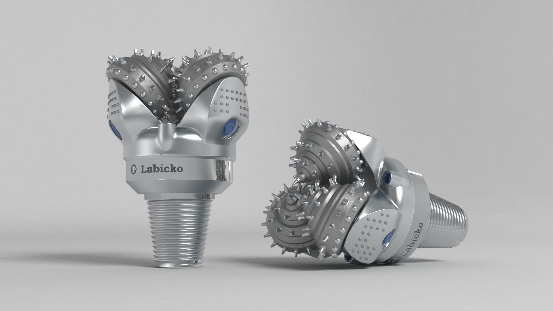
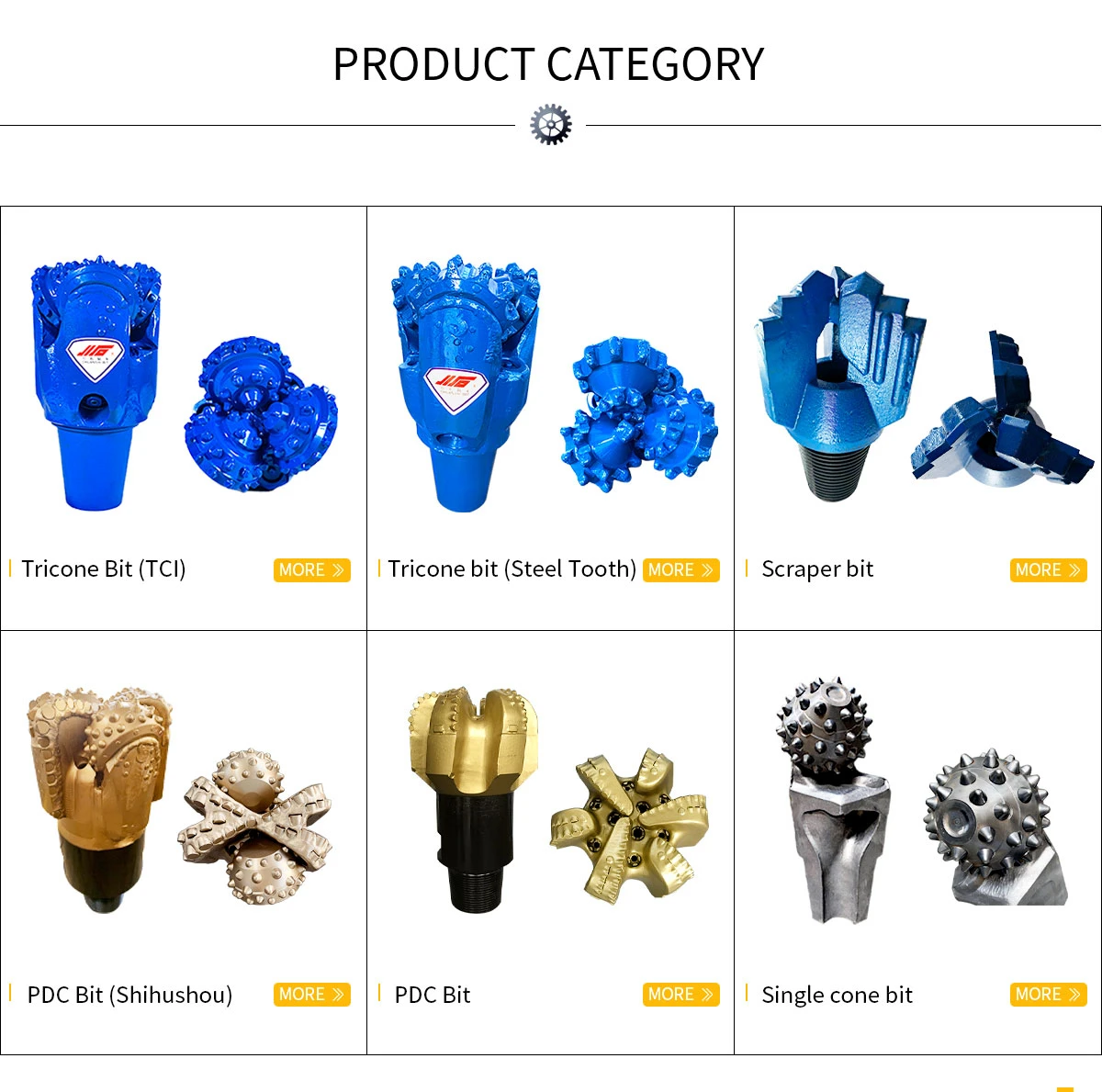
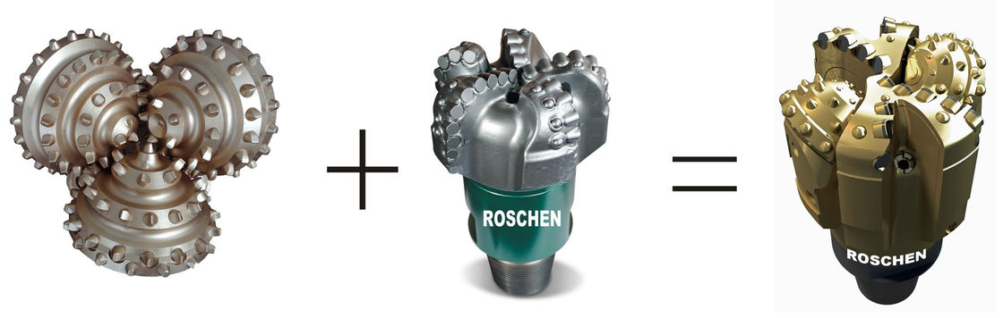
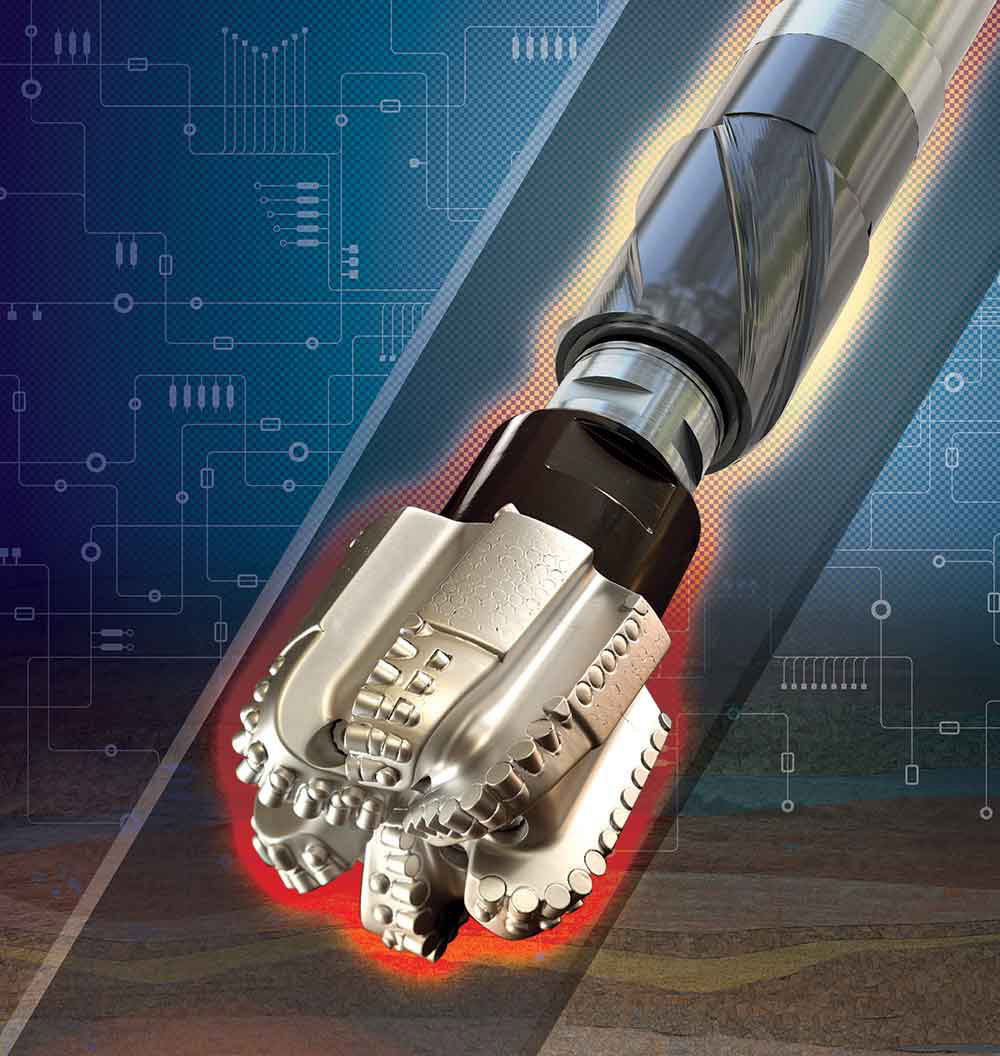
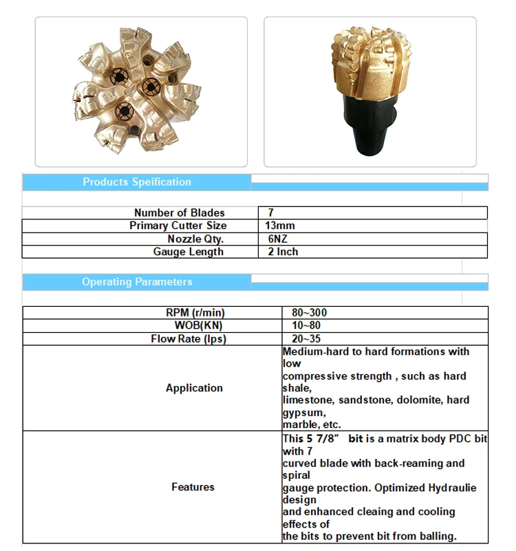
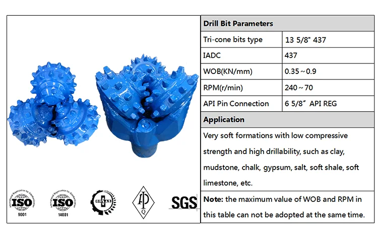
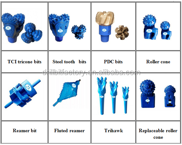
Tricone bits are used in general to drill a wide variety of rocks, from soft to extremely hard, while PDC bits can drill various sorts of formations, especially at harsh environments.
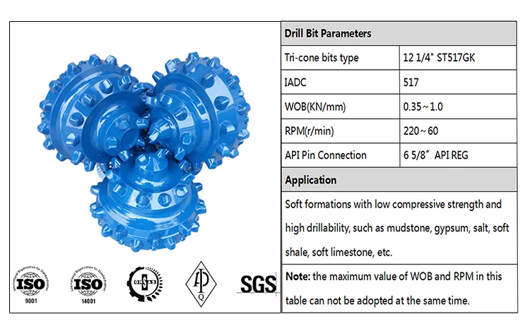
For Tricone bits drilling in moderate to hard formations, hydraulic horsepower (HHP) is the preferred optimization technique. As before a value of the power law exponent of 1.7, in the absence of calibrating data, is quite reasonable. Referring to Table 2.2 for the hydraulic power optimization technique, the optimized pressure loss across the nozzles is 63%, hence
If the same example rig with a 6000 psi pumping system were being used, the optimum pressure drop across a tricone bit should be 63% of this or 3780 psi. As with the case of jet impact, this level may or may not be entirely achievable.
For a fuller discussion of hydraulic horsepower optimization, please see the derivations section of this chapter.
As with the JIF optimization, once the TNFA has been calculated, then the sizing of the nozzles may be done via a lookup table such as Table 2.3 or with the equation previously given for identically sized nozzles.
Boyun Guo Ph.D , Gefei Liu , in Applied Drilling Circulation Systems , 2011
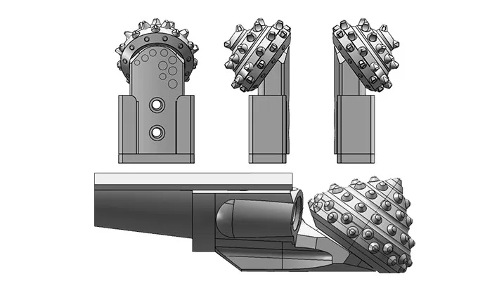
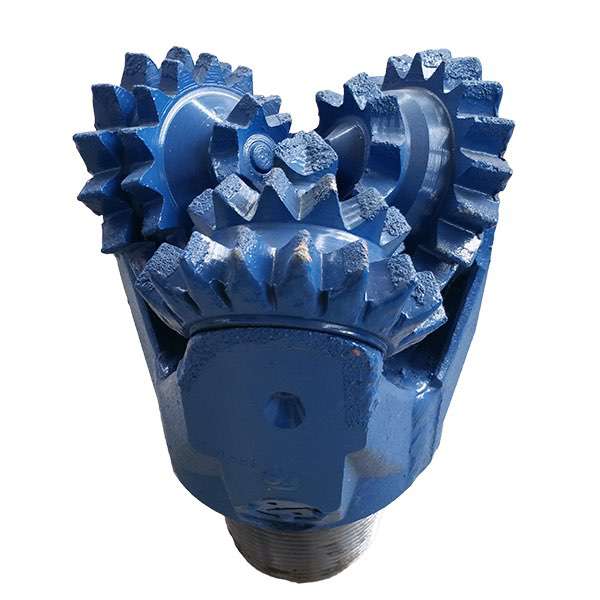
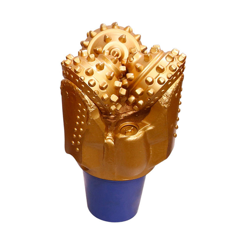
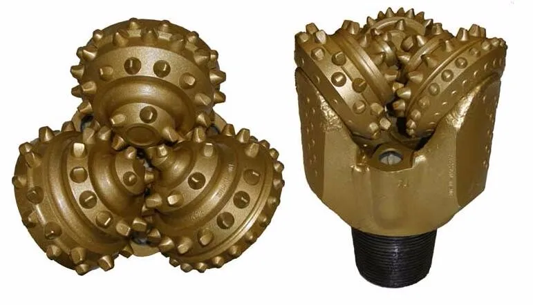
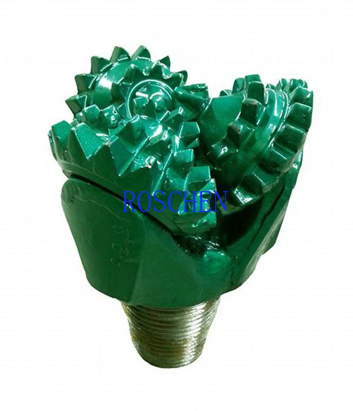
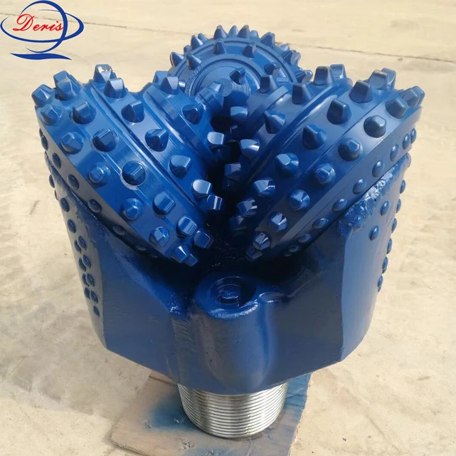
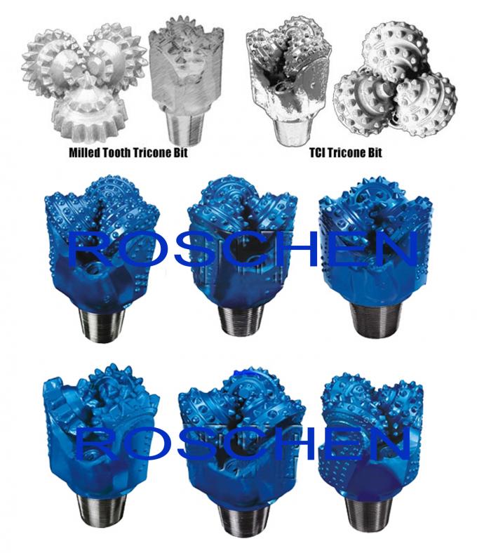
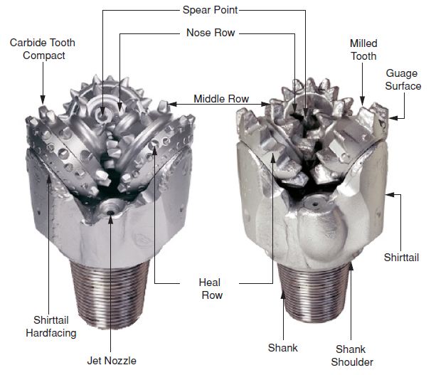
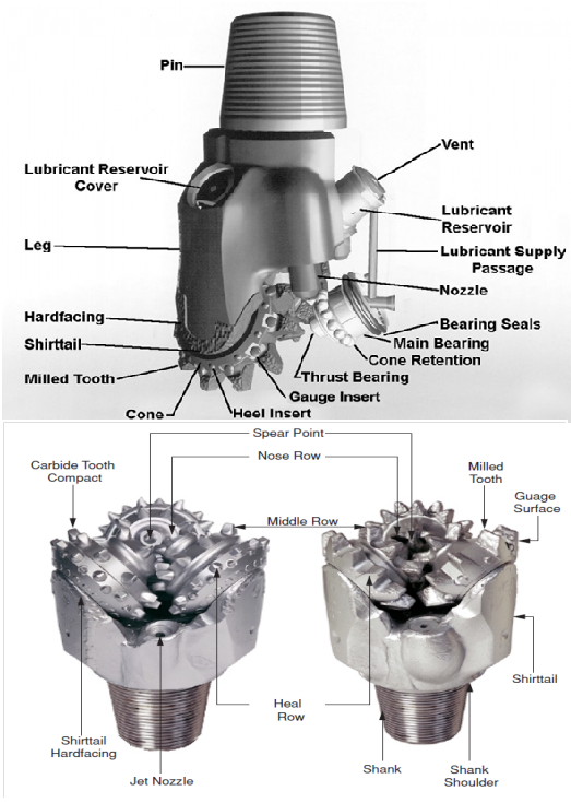
Figure 1.5 shows a drill string used in the oil and gas industry. The components of a drill string are described in this section according to the sequence in which they are run into the hole. A drill bit is installed at the bottom of the drill string. Three types of drill bits are used in the oil and gas industry: drag bits, cone bits (roller cutter bits), and PDC bits. Figure 1.6 shows two tricone bits , one with milled teeth and one with inserted teeth. Figure 1.7 shows a cutoff view of a tricone bit. Most bits are designed to install nozzles of different sizes. Drilling fluid passes through the bit nozzles at high velocity to clean the bit teeth and remove cuttings from the bottom of the hole. Figure 1.8 shows several types of bit nozzles, which are made of hard metal to resist erosion. Bit nozzle diameters often are expressed in 32nds of an inch. For example, if the bit nozzles are described as “12-13-13,” this denotes that the bit contains one nozzle with a diameter of 12 / 32 inch and two nozzles with diameters of 13 / 32 inch. Odd-numbered nozzles are not available for nozzle sizes above 20.
Figure 1.5 . A drill string used in the petroleum industry.
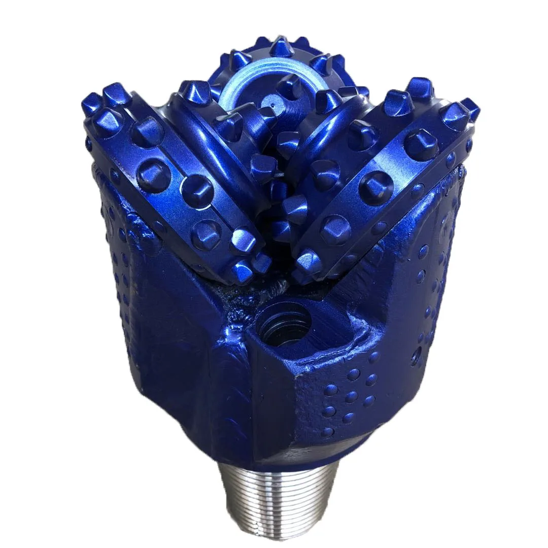
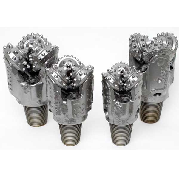
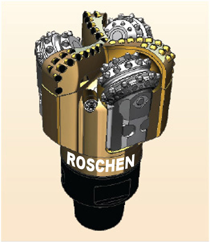
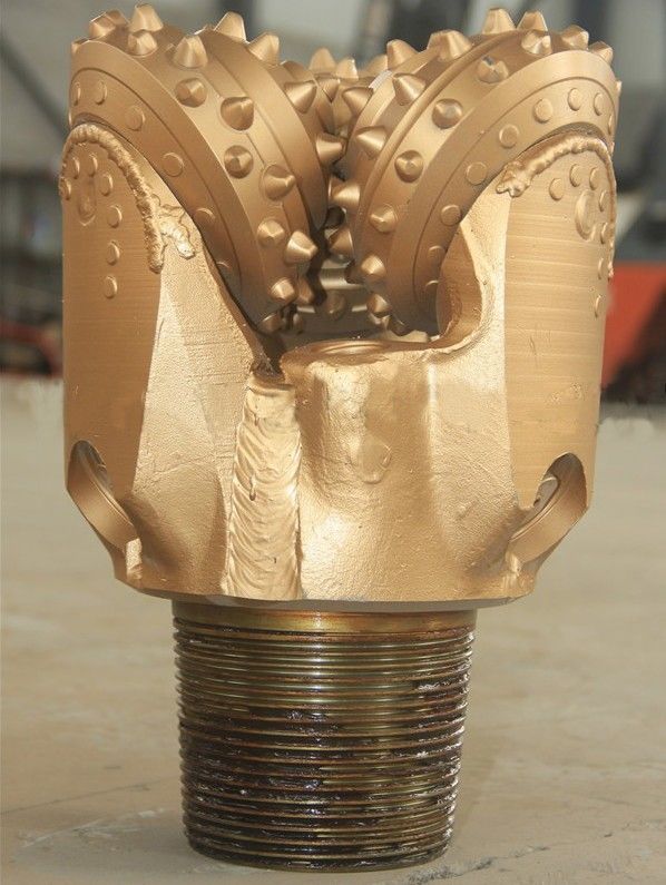
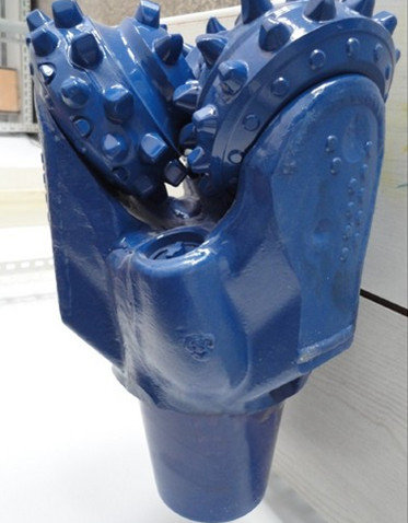
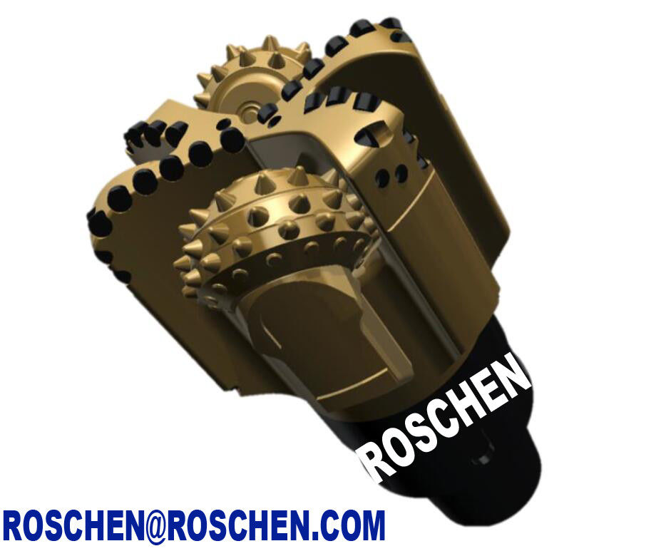
Figure 1.6 . Typical tricone bits used in the petroleum industry.
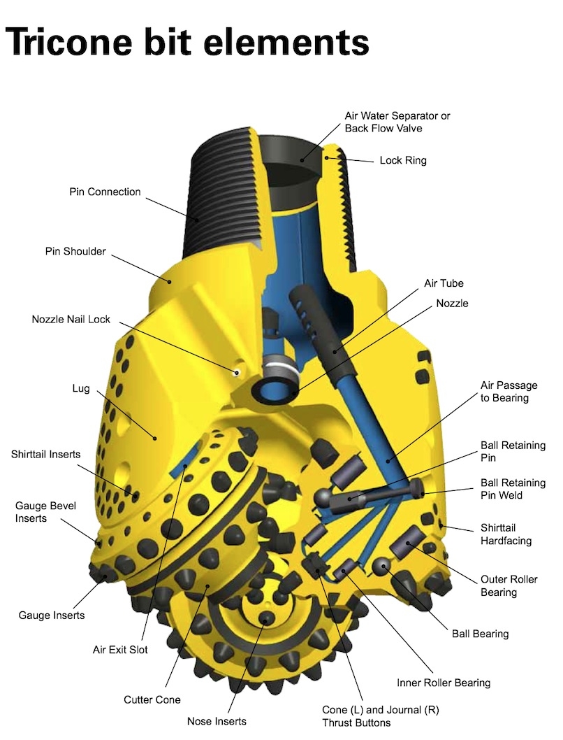
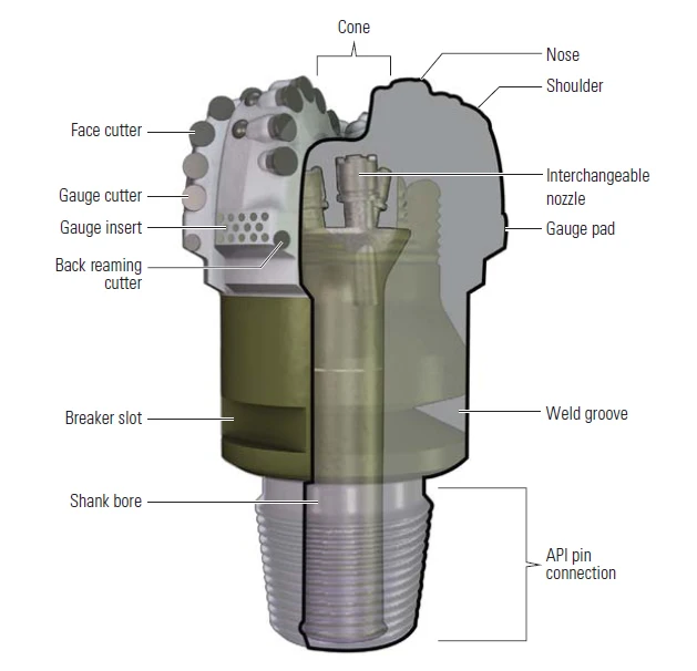
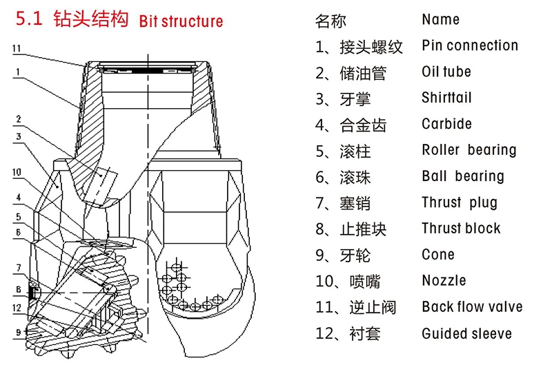
Figure 1.7 . A cutoff view of a tricone bit.
Figure 1.8 . Cutoff views of bit nozzles.
The drill bit is connected to drill collars through a bit sub, which is a short, thick wall pipe that has a threaded box on both ends. The bit sub is used for protecting the bottom threads of the bottom drill collar from wear due to the frequent drill bit connections. A drill collar is a thick wall pipe that gives weight to the drill bit, allowing the drill bit teeth to cut into the formation rock. Drill collars form a bottomhole assembly, with stabilizers installed at different distances from the bit ( Figure 1.9 ) to control the well trajectory. The number of drill collars in a BHA depends on how much weight must be applied to the bit to make it advance efficiently ( Bourgoyne et al., 1991 ). For directional and horizontal drilling, the BHA also includes mud motors and tools for measurements, such as measurements while drilling (MWD) and logging while drilling (LWD). The major components of a mud motor are shown in Figure 1.10 . A pressure drop of a few hundred psi is required at the motor to generate torque for the rotating drill bit.
Figure 1.9 . A bottomhole assembly used in the petroleum industry.
Figure 1.10 . The major components of a mud motor.
The drill pipe joints are above the BHA. The threads of the drill collar connections are usually not the same as the threads at the ends of the drill pipe joint. A special crossover sub is used to connect the drill pipe to the collars. The number of drill pipe joints used depends on the depth of the borehole. Conventional drill pipe joints are not designed to work in compression. After being pulled out of the hole for bit changes or well logging operations, the drill pipe string is broken into stand-by-stand sections and placed vertically between the drilling floor and the monkey board ( Figure 1.11 ). The length of the drill pipe stands depends on the type of drill rig used. A stand usually contains two or three joints.
At the top of the drill string is the kelly cock sub. It is another crossover sub that is used to protect the bottom threads of the kelly. The kelly is a special type of drill pipe with a square or hexagonal cross-section. The rotary table grips the outside of the kelly and provides the torque to the drill string to make it rotate. As the borehole gets deeper, the drill pipe string is disconnected and a new pipe joint is added. The bottom thread of the kelly cock sub takes the wear of these repeated connections of drill pipe.
Above the kelly is a swivel sub that protects the swivel. Above the swivel sub is the swivel, which is split into two sections: a rotating section on the bottom and a nonrotating section on the top. The nonrotating section of the swivel is held in the mast by the traveling block and hoisting system. A sealed bearing allows the bottom section of the swivel to rotate, while the top section can be held in position by the traveling block. The swivel allows the drilling mud to flow through it to the rotating drill string.
For direct circulation, the drilling mud flows down the inside of the drill string to the drill bit, flows through the drill bit orifices (or nozzles), entrains the rock cuttings from the drill bit, and flows up the annulus between the drill string and the borehole. Once it reaches the surface, the mud is cleaned by the contaminant-removal equipment.
A typical rotary air drilling system comprises three separate units: a self-propelled exploration drill, a trailer mounted air compressor, and a casing driver. The casing driver may be incorporated as an integral part of the drill rig or be mounted separately. The drill unit may be crawler or truck mounted. Crawler mounting is generally preferred because of better traction when hauling the compressor unit.
A Schramm rotary air drill used at San Antonio de Poto ( Fig. 6.17 ) successfully sampled formations of glacial till and outwash material at drilling rates of up to 40 m/shift). Sample material was collected feeding the slurry through a cyclone separator ( Fig. 6.18 ). Important features of the Schramm drill are:
6.17 . Schramm drill rig – San Antonio de Poto glacial outwash, Peru.
6.18 . Sample collecting using cyclone separator – San Antonio de Poto glacial outwash, Peru.
hydraulically driven rotary drill head with hollow spindle and a speed range from zero to 100 rpm; the drill head is floating in order to prevent galling of drill rod threads when adding or breaking out tools
a feed carriage with a sufficient length of stroke to handle the required drills; the mast assembly is raised and lowered hydraulically; the operator control panel provides hydraulic control of bit pressure and feed rate
a heavy-duty crawler assembly with each track independently driven is controlled hydraulically for maximum manoeuvrability
a suitable power unit drives the displacement pumps, which transmit power to the tracks and various rig functions; engine levelling facilities are available for operating on slopes; an automatic shutdown control operates if the oil pressure drops to an unsafe level; a rear-mounted winch unit, hydraulically operated is an accessory piece of equipment to assist crawlers on steep slopes or through muddy ground.
The Schramm and similar drill types advance casing in pace with the drilling through the use of a casing driver. The driver is provided with a central vertical passage to accommodate the drill pipe. Each operation, drilling and driving is controlled separately, thus allowing the operator to vary and co-ordinate the drilling and driving functions to suit differences in the various layers penetrated. Formation cuttings are returned through the annulus between the drill pipe and casing. The ascending air velocity is regulated to suit the formations being sampled. The air pressure is also used to tap the casing through boulders or, if required, to exert the full power of the driver when drilling through unconsolidated formations. Either down-the-hole hammer or tricone bits are used to drill the overburden while driving the casing. Casing drivers, when not integral with the drill rig, may be provided with inexpensive mounting devices to suit a particular rig. They are usually designed for all weather conditions and easy field maintenance. The ‘Tigre Negro’ model 612 casing driver illustrated diagrammatically in Fig. 6.19 can be completely disassembled and reassembled in under two hours.
Drive shoes are made with a reinforced cutting edge and machined from heat-treated, alloy steel. They are designed to withstand high impact loads so that they can be used repeatedly for downward driving in tough ground. For upward driving, the sudden sharp bursts of energy applied to driving demand the use of a heavy-duty, thick-walled casing with strong threads. The disadvantage is that the sharp upward blows damage any threads that have become loose; even with the strongest of pipes, any looseness in the threads can cause them to break easily.
Casing pullers dramatically increase the available drilling time. While casing extraction is in progress on a completed hole, the drill can already be at work drilling the next hole. Using one casing puller in two separate operations (drilling and pulling), it was possible at San Antonio de Poto to average one hole/8 hr shift to a depth of 30 to 40 m. In another application in Papua New Guinea a simple casing puller was developed for a cable tool operation as described in Fig. 6.20 . The requirement was for a pulling pressure of 44 tonnes and a breaker pressure of five tonnes. The system was in two parts:
6.20 . Avenall casing puller (after Avenall, 1987 ).
Hydraulic power unit incorporating pump, reservoir, relief valves, controls and filter; the pump could be driven from a tractor power take-off or separate air-cooled engine.
Breaker puller unit comprising two hydraulic ram mechanisms mounted on the base plate; the spider and breaker are attached to the mainframe, which in turn connects to the jacks; this unit is attached to the power unit via hydraulic hose lines with quick-release couplings.
These systems rely upon high-pressure air or water to recover the sample cuttings. Air or water is introduced into the annulus between the two pipes to service a double wall drill string, top drive rotating head and side inlet swivel. If water is the medium, the return flow passes to a settling tank to recover the entrained solids. If compressed air is the medium, the cuttings pass to a cyclone- separating unit for recovery. Water circulation systems are generally less satisfactory than compressed air systems. The Wallis drilling air core system, as illustrated in Fig. 6.21 is designed around the principle of reverse circulation; the sample being returned up a concentric inner tube.
6.21 . Wallis air core drilling system.
Experience with the Schramm drill at San Antonio de Poto, showed that no undue sampling problems occurred in moderately moist gravel horizons with up to 40% clay content. For an air discharge velocity of 20 m/s a 1.0 m sample interval at 30 m depth could be cleanly blown in from five to eight seconds, the cyclone interior being reasonably clean after recovering the sample. However, pressure hose fittings and in the provision of a latch to hold the respective pieces together while drilling layers containing wet clay and coarse gravels were difficult to sample. Plugging occurred in elbows of the sample discharge line above the drill head exit and in the tricone bit at the bottom of the h
Bit Dull Grading Steps & IADC Handbooks - TriCone PDC - Drilling Manual
Tricone Bit - an overview | ScienceDirect Topics
Simulating a Tricone Drill Bit with CONVERGE - YouTube
Practicality of Tricone Bit Wear Condition Assessment | Cambridge Core
Tricone drill bits | Baker Hughes
Краска Kapous Пепельный
Краска Эстель Светло Русый
Keune Для Укладки Волос
Calculation Of Kinetics Tricone Drill Bit