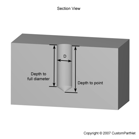
Blind Hole

👉🏻👉🏻👉🏻 ALL INFORMATION CLICK HERE 👈🏻👈🏻👈🏻
A Blind hole requires reference face to the hole opening (ring) relationship to be stored.
S.T. Lin , C.P. Hu , in Non-destructive Testing '92 , 1992
The blind-hole method is the widest used method for measuring residual stresses[ 1 ]. In general, a strain gauge rosette is required for one application of this method. But, many drawbacks arise with the procedures of mounting the strain gauges on the surface of the material. Polishing, bonding and soldering are all necessary but take a significant amount of time. As well, there is no method which can be used for assuring the bonding conditions. That is, the strains at the material surface may not be the same as at the strain gauges for error bonding conditions. Moreover, the hole center is very difficult to place on the center of strain gauge rosette precisely. However, even a small misalignment of the hole drilling will result in large errors of measured stresses.
Some of the difficulties associated with the use of strain gauge rosettes(i.e., inaccuracies caused by off-center holes) may be overcome through the use of a photoelastic coating technique[ 2 ]. By reading the fringe order shown on the photoelastic film which is coated on the surface of material, the residual stresses can be determined after hole drilling. In addition, moire' interferometry[ 3 ] can also be used to measure in-plane displacements due to hole drilling, which needs one grating mounting on the surface of the material and one grating for reference. From these measured displacements, the residual stresses can then be determined. However, both coating a photoelastic film and mounting a moire' grating on the surface of the material are difficult and time consuming. As a result, holographic interferometry is considered in this paper. By the help of finite element calculations, it becomes an easier, more useful technique.
A microvia is a blind hole drilled in conductor-insulator-conductor multilayer to provide electrical connection through insulator in electronic circuits. The density of such microvia holes is around 1202 interconnection cm −2 in current mobile phones and camcorders ( 9 ) . Microvia holes of diameter bigger than ∼150 μm can be done by a mechanical drilling process, but below 200 μm the cost of this process increases drastically. The demand for increasing the speed and memory of circuits has necessitated increasing the electronic circuit density and, correspondingly, interconnection density in a chip. Laser drilling of microvias of diameter less than 150 μm is displacing the mechanical drilling and now occupies around 94% of the market ( 6 ) . The rf excited slab CO 2 or TEA CO 2 laser and ultraviolet lasers (either excimer or higher harmonics (355 or 266 nm) of Nd:YAG laser) are mostly used for this application. Since copper is highly reflective at 10 μm, Q-switched Nd:YAG lasers (fundamental or 3rd-harmonic) are used to drill the upper copper layer, while either CO 2 (rf-excited or TEA) or 3rd-harmonic YAG laser is used to drill the dielectric material. When drilling blind microvias, CO 2 lasers have the advantage that the drilling naturally selfterminates at the copper layer below without damaging it. Figure 71 shows the two step laser drilling of blind microvia. In the first step, a 100 μm hole is produced on the top copper layer by Nd:YAG laser trepanning, and in the second step the dielectric material is removed by a CO 2 laser ( 9 ) .
Figure 71 . Blind microvia of 100 μm diameter drilled in a PCB. (a) Step 1, Nd laser trepanned hole in top copper conductive layer. (b) Step 2, CO 2 laser drilling of fiber reinforced composite FR4 layer to copper below.
M. Aliofkhazraei , N. Ali , in Comprehensive Materials Processing , 2014
The design should lack any deep and blind holes and cavities.
Small holes are difficult to plate. The piece has to be preferably designed in a dividable manner.
The holes or cavities have to be coated with a width to depth ratio of 1:1, although the wider ratios are preferable.
It is required to remove all surface cavities. The piece is not allowed to be porous or with slots or openings.
No chip is allowed to be in the edges of the coated surface.
The components have to be montaged by their bolting or contraction interdispersion.
Large surface section difference leads to temperature difference in the process and has to be avoided.
Coating has to be performed in a mechanical manner and since it has to be very strong and adhesive during the installation, design accuracy and maybe consulting with the contractor is necessary.
Some accessory devices might be required to hold the piece. Here, it is required to consult with minor contractor.
N. Depaiwa , ... S. Ochiai , in Human Friendly Mechatronics , 2001
The objective task is to make a small-diameter blind hole onto an aluminum workpiece with a carbide drill. The cutting conditions are shown in Table 1 . This is a difficult task for even skilled operators as well as unskilled ones, because the drill flutes are apt to be choked with the cutting chip and the drill often breaks. As a machine tool, an NC milling machine in manual operation mode was adopted in order to remove the influence of force sensory feedback. That is to say, since its handwheel is just connected with a pulse generator for spindle feed, the operator cannot feel cutting force through the handwheel at all. In addition, no auditory feedback exists either, because loud sound of the main spindle motor prevents the operator from hearing cutting sound. Accordingly, only the visual feedback, or view of the cutting chip flow, drill breakage, etc., exists basically in this task.
Table 1 . Conditions of objective task
Figure 1 shows the active visual feedback system of cutting force for drilling. The force is detected with a strain gauge type dynamometer and input to a personal computer. The computer processes the force information and displays it on a screen of HMD which the operator wears. The force information is very important for the operator to complete the task safely and swiftly. And, the active visual feedback system of cutting force is constructed. As for the HMD, both a binocular one (Virtual i-Glasses, Virtual i-O Personal Display Systems) and a monocular one (Data glass, Shimazdu Corporation) were examined. The operator can see the drill and workpiece themselves through HMD because of see-through type. Data glass is a see-through see-around type and the operator can get also a view around the screen of HMD.
Fig.1 . Active visual feedback system using HMD for minute drilling
The cutting force is detected as thrust (axial) component and torque (rotational) component. Figure 2 shows examples of the detected force. The small pitch fluctuation is mainly caused by rotation of the drill (8.33 r/s). Though a low pass filter of 1 Hz is used for the measurement, this fluctuation still appears because of dominant component in the signal. From these examples, it can be noticed that the thrust rapidly increases in the early stage of the task. In addition, the torque largely fluctuates in the cause of drill rotation and its amplitude gradually increases. Figure 2(b) shows the force signal when drill breaks during task. As can be seen, the breakage occurs at the thrust of about 40 N and the torque of about 0.8 Nm. In many cases, the breakage occurs around these values of thrust and torque. However, every breakage doesn’t occur at exactly the same values.
On HMD, the value of either thrust or torque as feedback information is displayed by a chart image. Figure 3 shows four kinds of charts examined in this research. In both bar charts, the length of the red bar inside a fixed rectangular frame corresponds to the value of the force. In the sector chart, the angle of the red sector corresponds to it. In the circle chart, its diameter corresponds to it. The length of the frame in the bar charts is made 40 N for thrust and 0.8 Nm for torque, and the sector angle 135 degree in the sector chart is made similarly. In any chart, its size and position in the display screen can be adjusted by the operator, if it like. The sample of HMD image which the operator sees is shown in Figure 4 . The updating interval of feedback information is less than 33 ms for all charts despite their position and size.
Fig.3 . Chart images for active visual feedback
To overcome the problem of limited space, multilayer boards may make use of through-hole, blind, and buried vias . A through-hole via passes all the way through the board, a blind via is visible from only one side of the board, and a buried via is used to link internal layers and is not visible from either side of the board ( Figure 18.18 ).
Figure 18.18 . Through-hole versus blind versus buried vias.
Unfortunately, although they help to overcome the problem of limited space, blind and buried vias significantly increase the complexity of the manufacturing process. When these vias are only used to link both sides of a single sub-board, that board must be drilled individually and a plating process used to line its vias with copper. Similarly, in the case of vias that pass through a number of sub-boards, those boards must be bonded together, drilled, and plated as a group. Finally, after all of the sub-boards have been bonded together, any holes that are required to form plated through-holes and vias are drilled and plated. Blind and buried vias can greatly increase the number of tracks that a board can support but, in addition to increasing costs and fabrication times, they can also make it an absolute swine to test.
Sound absorption perforated gypsum board achieves the effect of sound absorption by making use of the blind holes , the perforated holes in the board and the sound absorption materials on its back, as well as the embossed patterns of certain thickness, so different structures of perforations, materials and embossed patterns develop different sound absorption effects. To buildings with ordinary sound absorption demand, it is suitable to use decorative sound absorption gypsum board. When higher sound absorption is required, sound absorption perforated gypsum board should be selected, and embossed panel coincided with perforated board can also be adopted.
Sound absorption perforated gypsum board is mainly used in the sound absorption structure of indoor ceilings and wall bodies. In installation, the arrow on its back should be in the same direction with the white line in order to keep the integration of the patterns. Proper moisture proofing, water resistant or fire resistant base plate should be adopted in humid environments or when higher fire resistance is required. Sound absorption perforated gypsum board has such properties as light weight, fire proofing, sound insulation, heat insulation, good vibration resistance, and can be used to adjust indoor humidity. With good process-ability, it is convenient in application and fit for dry operation, which saves labor and results in higher construction efficiency.
Sound absorption perforated gypsum board is used as the primary sound absorption decorative material for the decoration of suspended ceilings and walls at places where higher acoustic quality is required or where noises are severely limited, such as broadcasting studios, concert halls, theaters and conference rooms etc.
Heinz P. Bloch P.E. , Fred K. Geitner P.ENG. , in Machinery Component Maintenance and Repair (Fourth Edition) , 2019
Health and safety measures must always be regarded during the cleaning and priming procedures. When a pin is driven into a blind hole , care should be exercised to see that excess quantities of the sealant have not built up in the bottom of the hole. Hydraulic pressure may be developing, resulting in cracked castings.
Thread locking compounds will soften vinyl, cellulosic, styrene, and methacrylate plastics. Contamination with metal particles will harden the compound contained in bottles. Do not dip metal parts or brushes into the bottle or return contaminated liquid to the bottle after using. Do not mix primers with the compound as this will cause them to harden.
Bottles of LOCTITE, for example, are oversized to provide an air space that must be maintained above the liquid level to prevent the compound from curing until it is applied. Do not pour bottles full, or the compound will harden.
Maintain liquid compounds at 68 ± 20°F or 20 ± 10°C for maximum shelf life. When stored under these conditions, a 1-year shelf life may be expected. If in doubt, the thread locking compound manufacturer should be consulted.
The primer should be applied by dipping, spraying, or swabbing. Allow it to dry until it is free of solvent odor, 3 min at 75°F or 25°C, 5 min at 40°F or 5°C, and 1 h at 10°F or − 10°C. Do not wipe it off. Upon evaporation, it leaves a light catalyst that speeds hardening and insures complete curing of the locking compounds. The strength of cured locking compounds is reduced by 15% when a primer is used. Apply locking compound now. It is necessary to apply it to only one of the mating surfaces; however, both surfaces must be clean and dry. The compound may be applied to male surfaces by dipping, brushing, using spray applicator, a stamp moistener, or directly from the bottle, prior to assembly.
Assemble parts. Since the thread locking compound is an anaerobic material, it remains liquid while exposed to air. Treated parts can be easily assembled with hand tools. Studs, bolts, and pins are easily driven, with locking action developing after they are in place. Allow it to cure according to Table 8-6 before placing in service.
Table 8-6 . Typical cure time of locking compounds (at room temperature)
Notes: (1) Heat may be applied to speed curing; do not exceed 300°F (150°C).
(2) Cure speed is reduced at lower temperatures.
The design of packaging should also consider how easy it is to decontaminate. The use of radiused internal corners, avoidance of blind holes , and if at all possible, tapped holes will make radiological monitoring easier; if decontamination is required, that will also be easier.
The effort that is required will depend on the cleanliness of the environment in which the packaging operates. Spent fuel pond water will gain ingress to any unsealed cavity and carry contamination with it.
The regulations state that this should be achieved ‘as far as practical’. It is essential to involve health physics monitors at the design stage.
The weld should be smooth as laid. Grinding with subsequent polishing is expensive and may create micropores as the asperities of the surface are turned over.
The use of decontaminable paints should also be considered. The removal of contaminated paint is easier than removing layers of metal.
Consideration should be given to making feet removable (particularly heavy packages). Therefore, if contamination is ground into the surface removal of the foot, the contaminated area can be easily decontaminated. (This does still leave a contaminated item for disposal.)
FIB microhole drilling was originally published by Sabaté et al. in 2007a and is based on the miniaturization of the classical macroscale blind hole drilling method originally developed by G. Schajer (1988) . This approach provides a measure of the 2D stress state in the surface of interest by milling a small circular hole into the sample surface ( Fig. 9.6B ). The DIC of the surrounding region is used to quantify the strain relief field induced by milling to provide an estimate of the stress state originally present. Microscale hole drilling has the benefits of being experimentally simple and fast, and depth-resolved extensions of this technique have been reported ( Winiarski and Withers, 2012 ).
Despite these improvements, microscale hole drilling relies on the DIC analysis of the stressed regions outside the gauge volume location, and therefore is subject to reduced gauge volume precision in a way similar to microslotting. Another difficulty associated with this experimental approach is the limited amounts of strain relief induced by milling. The impact of noise on the perceived residual stress value(s) is therefore far greater than for other methods, and the solution of the inverse problem associated with this technique requires careful regularization ( Winiarski and Withers, 2012 ). Regularization not only reduces unrealistic variations in the stress values obtained, but also limits the sensitivity of the technique.
Liquid solvent just “flies off” ( Figure 1.28 ) simple surfaces in response to a large difference in temperature between the solvent's normal boiling point and the air temperature between the cooling coils.
Figure 1.28 . Hyropthetical Arrangements Within an OTVDG – Showing How Drying is Accomplished
The operative word is “simple.” Surfaces which are flat, and don’t have crevices, pockets, cracks, blind or tapped holes, cupped structures, or knurled surfaces are those identified as “simple.” Simple surfaces don’t trap droplets of liquid. Simple surfaces are wet with films which evaporate rapidly.
Complex surfaces will require extension of the cycle time to allow trapped liquid to be evaporated.
Note the position of the parts basket in Figure 1.28 – it is above the vapor cloud (zone) but within the volume affected by the cooling coils.
That location might not continue if the parts basket continues on an upward trajectory attached to the hoist before the liquid collected in complex surfaces is vaporized. In that case, three negative consequences will eventuate:
Liquid evaporated when the parts are outside the zone affected by the cooling coils will become pollution (possibly harming workers), and
Operational cost will be increased.
We use cookies to help provide and enhance our service and tailor content and ads. By continuing you agree to the use of cookies .
Copyright © 2021 Elsevier B.V. or its licensors or contributors. ScienceDirect ® is a registered trademark of Elsevier B.V.
NC milling machine MAKINO AV III NU-85 (Manual operation mode with a handwheel)
Возможно, сайт временно недоступен или перегружен запросами. Подождите некоторое время и попробуйте снова.
Если вы не можете загрузить ни одну страницу – проверьте настройки соединения с Интернетом.
Если ваш компьютер или сеть защищены межсетевым экраном или прокси-сервером – убедитесь, что Firefox разрешён выход в Интернет.
Время ожидания ответа от сервера handwiki.org истекло.
https://www.sciencedirect.com/topics/engineering/blind-hole
https://handwiki.org/wiki/Engineering:Blind_hole
Made In Canarias Anal Sex 2021
Nylon Knee Sock Video Erotic
Medical College Party
Blind Hole - an overview | ScienceDirect Topics
Engineering:Blind hole - HandWiki
Blind Holes - All About - MachinistGuides.com
What is BLIND HOLE? What does BLIND HOLE mean? BLIND …
What is a Blind Hole? - wiseGEEK
Difference between through hole and blind hole on ...
Hole - Wikipedia
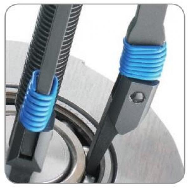
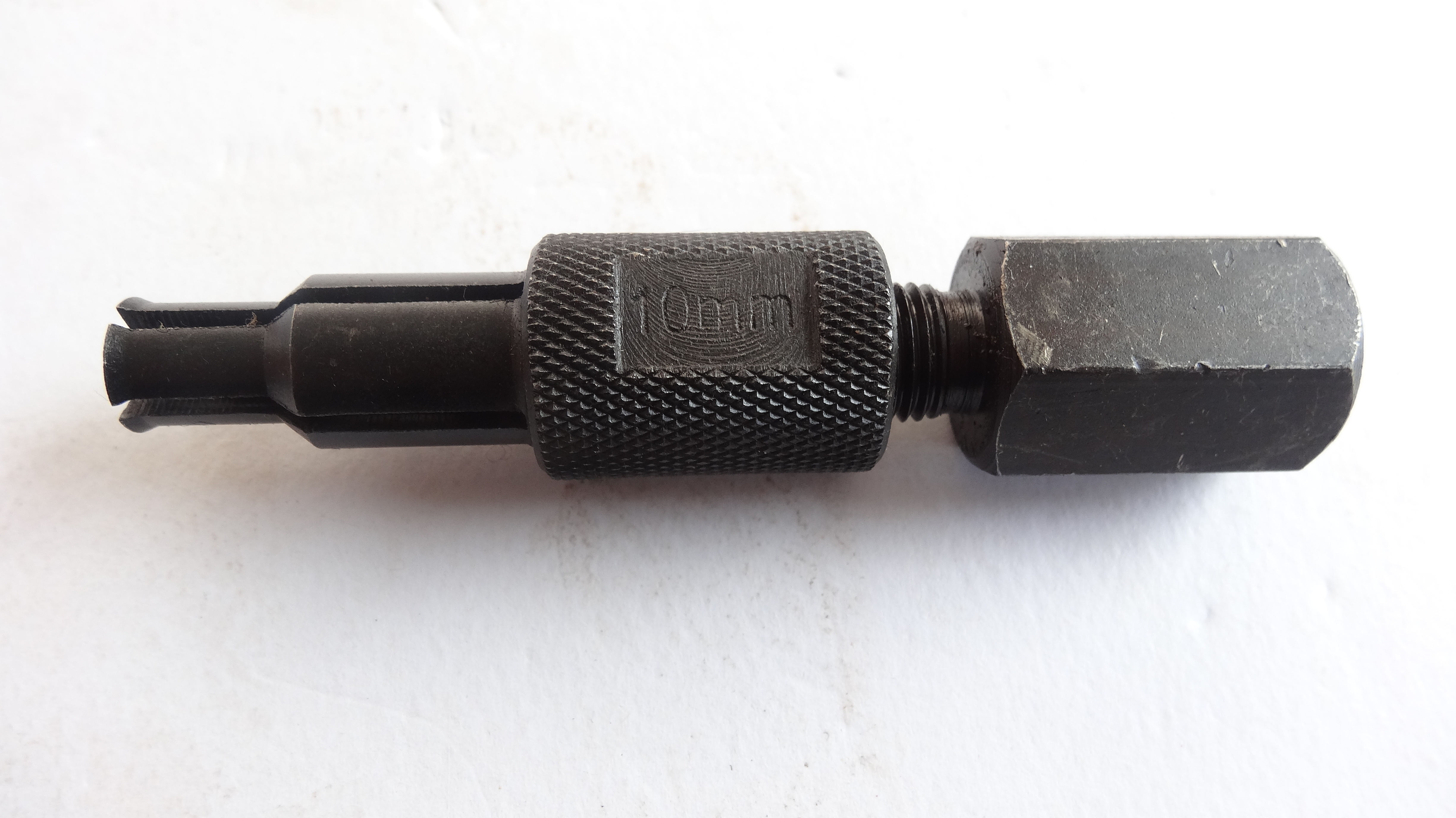
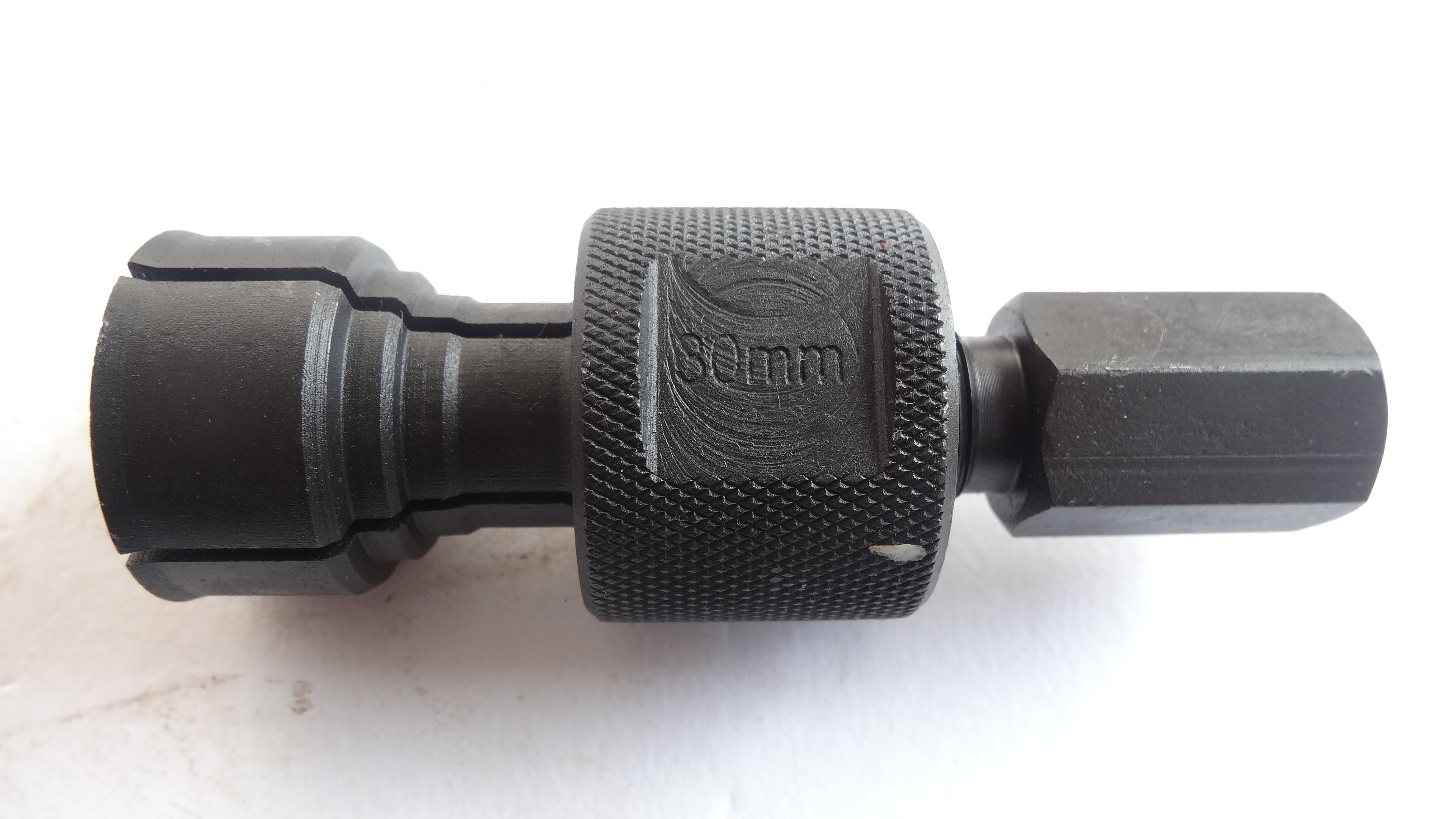
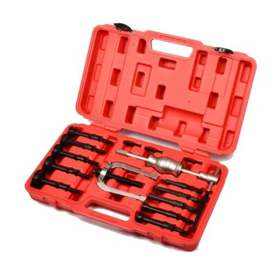
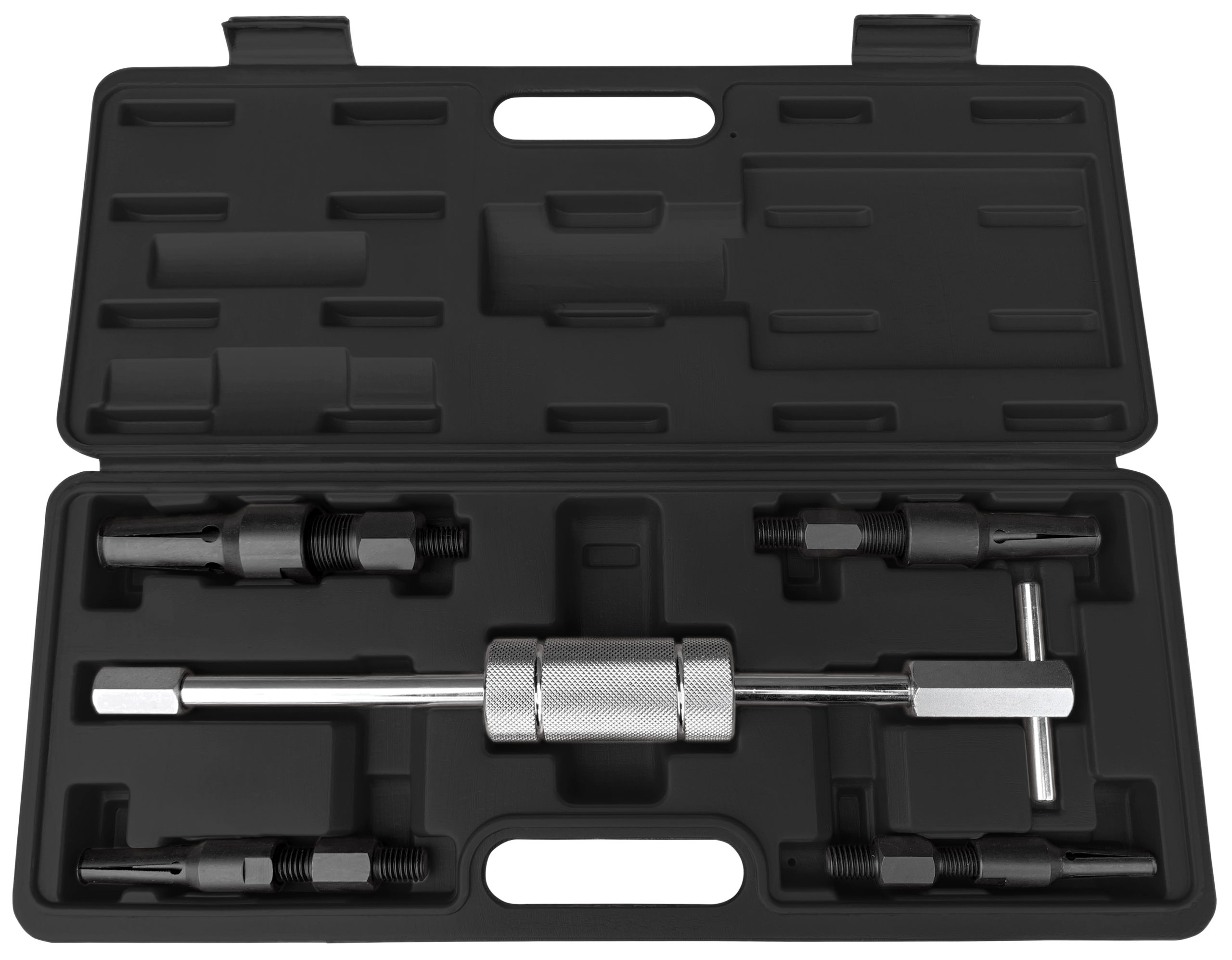
How to Extract Blind Hole Bearings - YouTube
Blind Hole Oval Rubber Grommets - GTeek
Golf: Blind Hole - Definition
Blind Hole