Bios Spread Spectrum

🔞 ALL INFORMATION CLICK HERE 👈🏻👈🏻👈🏻
Bios Spread Spectrum
What is clock spread spectrum in the BIOS settings?
Learn what basic & advanced features to consider for a chat API.
Inside this Chat API guide, you will find the insights to help you leverage a Chat API for your business.
Updated January 14, 2021 · Author has 2.4K answers and 2.3M answer views
What is clock spread spectrum in the BIOS settings?
Did you know you can find almost anyone's public records?
View public records for arrests, criminal, addresses, marriage, property, deaths & more!
Does spread-spectrum clocking degrade a CPU's performance and cause it to operate at higher temperatures?
I want to allocate more RAM as VRAM on an ASUS X555Q Notebook, however the BIOS has no options for graphics. How do I do this?
Is 16gb of Vram necessary for the Radeon 7? Why or why not?
Where are your BIOS settings stored?
Answered 3 years ago · Author has 1.3K answers and 772.5K answer views
Are any distant objects so red-shifted that we can see their X-ray emissions in the visible spectrum?
What kind of implications and how wpuld have things turned out if we heard a computer which processed information using a ternary code e.g. (-1,0,1) system instead of binary code(0,1) system and what kind of a quantum system would have been develop?
Answered 1 year ago · Author has 7.1K answers and 5.4M answer views
What does happen when we run out of space on the radio frequency spectrum(s)?
How do I enable VT-x in my BIOS settings?
How do I get to the BIOS settings without rebooting?
What the key features of LTE radio access concerning carrier technology, antenna, spectrum and interface?
How do I show hidden BIOS settings?
Answered 1 year ago · Author has 8.6K answers and 76.9M answer views
Answered 2 years ago · Author has 94 answers and 49.4K answer views
Do elements absorb invisible frequencies in the absorption spectrum? Why is it insignificant?
Why is each element's emission spectrum unique?
Answered 9 months ago · Author has 2.1K answers and 1.1M answer views
What three wavelengths are emitted by the RGB pixels of standard displays?
Answered 5 years ago · Author has 423 answers and 555.8K answer views
Answered December 18, 2020 · Author has 5.4K answers and 976.1K answer views
What determines the spread spectrum?
Answered 2 years ago · Author has 280 answers and 94.4K answer views
What do the lines in an emission spectrum represent?
Does spread-spectrum clocking degrade a CPU's performance and cause it to operate at higher temperatures?
I want to allocate more RAM as VRAM on an ASUS X555Q Notebook, however the BIOS has no options for graphics. How do I do this?
Is 16gb of Vram necessary for the Radeon 7? Why or why not?
Where are your BIOS settings stored?
How do I enable VT-x in my BIOS settings?
How do I get to the BIOS settings without rebooting?
What the key features of LTE radio access concerning carrier technology, antenna, spectrum and interface?
How do I show hidden BIOS settings?
What type of games can I play on a core i7 6500U with 16GB RAM, 2.5 GHz?
Why can't computers access certain sites when the clock is off?
Why is CDMA called a spread spectrum?
What is the VRAM (graphic memory) of a 4GB RAM laptop?
Does spread-spectrum clocking degrade a CPU's performance and cause it to operate at higher temperatures?
I want to allocate more RAM as VRAM on an ASUS X555Q Notebook, however the BIOS has no options for graphics. How do I do this?
Is 16gb of Vram necessary for the Radeon 7? Why or why not?
Where are your BIOS settings stored?
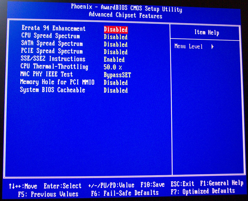
What is clock spread spectrum in the BIOS settings?
A computer’s clock is an electronic signal that goes up and then goes down at a particular rate (frequency) and controls and synchronizes the operation of the CPU and motherboard. It is essentially the “heartbeat” of the computer. It is measured in Hertz (Hz - changes per second) and typically, computers operate at Gigahertz clock speeds today (GHz), which is a billion Hz.
The clock is generally the fastest signal in a computer. Because of it’s speed, it generates a lot of Electo-Magnetic Interference (EMI) , which is also called Radio - Frequency Interference (RFI) when in the radio frequency spectrum, collectively we’ll call electronic noise. This can cause other devices (e.g. AM radios, speakers, TV’s, amplifiers etc) to pick up this noise as static noise or video glitches. The Federal Communication Commission (FCC) regulates this noise, and limits the maximum allowed.
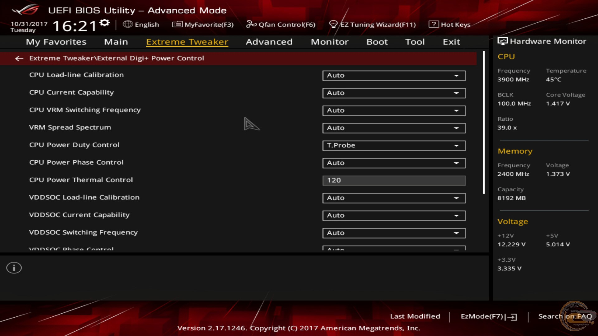
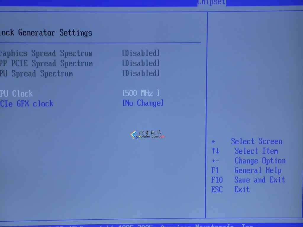
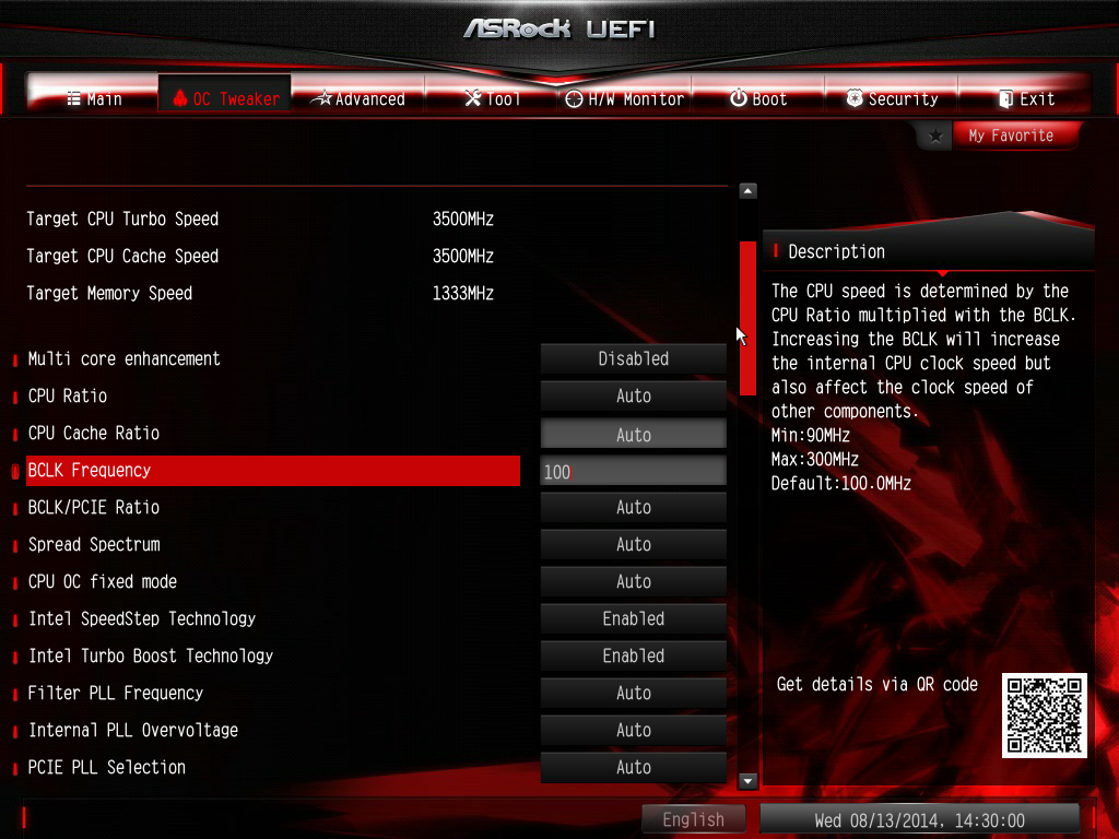
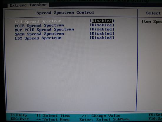
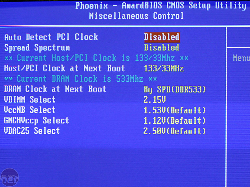
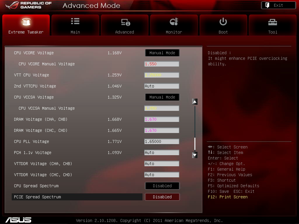
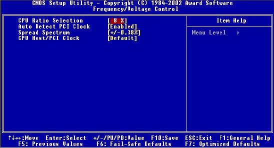
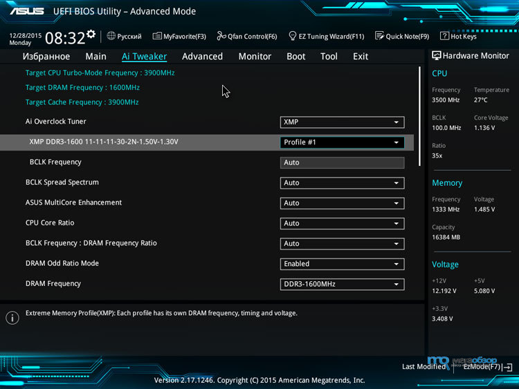
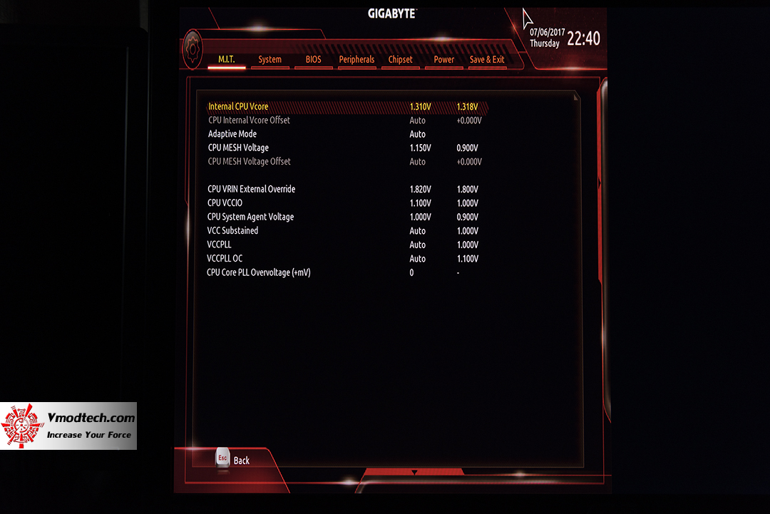
The BIOS (CMOS) Setting for clock spread spectrum affects the system’s clock. While the speed stays the same, it adjusts the exact points that the clock signal goes up and goes down, somewhat randomizing these points. This tends to spread the noise over time and frequencies, and thus reduce the overall maximum noise. So normally you want to enable this, as there is no speed penalty, and you reduce electronic noise.
The above picture (energy at frequencies around a reference base frequency), from this page, EMI Reduktion Spread Spectrum Clock Oscillator , shows the electronic noise is reduced (in red), and spread across multiple frequencies, rather than all at one frequency (blue).
SB’s Q: “ Are any distant objects so red-shifted that we can see their X-ray emissions in the visible spectrum? ”
2002 Nobel Prize in Physics Awarded to Riccardo Giacconi for the Discovery of X-ray Emission from Celestial Sources.
From Giacconi’s work we might understand what is possible to determine if x-ray emitted from distant objects is (red)shifted enough to view on the visible light spectrum:
X-ray being an (ESE) Electromagnetic Spectrum Energy(ies), should fall prey to the same affects as any ESE. If it is (red)shifted enough to show as visible light, that may be very difficult to detect or find daat to prove it. But its worth the effort, an award could be it the finding.
The object would have to be near enough that visible light is still available from it, as X-ray emissions would be shifted, as is all ESE, and become visible ESE.
Gleaning that my Equation indicates all ESE is (red)shifted traveling in a gravity field, then X-ray should be detected (eventually) first as Ultraviolet and eventually then as visible light.
Take note, we see redshifted light from distant galaxies disappear to be detectable via infrared. That should answer your question if you follow the logic and Equations explanation.
But does X-ray ESE become (red)shifted to be visible light?
That is a good question, and intensity may play a logical reason in such.
We understand that distant disappearing galaxies get redshifted from view and become detectable via near infrared. Indicating my Equation confirmed in such data.
The peak radiation (ESE) intensity is at the visible light spectrum (emission) portion of the spectrum. Visible light (intensity) is perhaps the last to go/disappear when shifted, then the shifted backgrounds we detect are shifted (visible light) photons. Ergo, that is what will be detected last and what we detect as ESE (red)shifted of the background maps. That is why i put the first pic in this answer:
The bright side is x-rays emission from the sun reflected from the moon to earth satellite observer. And, from the dark side to the bright side, we can deduct the moon may be a reflector of near by emitted x-ray, but it is not a emitter of x-ray, and, there is not much X-ray to reflect from the distant X-ray emitting sources. This leaves little else to conclude other than X-ray gets shifted from detection in a gravity field first from the distant before the close emitter. The pic confirms it.
We may conclude X-ray is shifted enough from other sources that few reflect from the dark side of the moon. This follows the same logic as visible light photons and the Equations (red)shift explanations and why there is a dark side and light side. If light or any ESE did not (red)shift in the gravity field, the Universe, then the dark side would not appear so dark.
And, if you will please notice, the dark side is darker than the background detections. This has indications also.
The Cosmic X-ray Background (CXB), akin to the Cosmic Microwave Background (CMB), is looking at X-ray background the same as the microwave background. The CMB or the CXB peaks the same as the entire ESE spectrum peaks, this has indications also.
Intensity is an fine issue to address, and finding X-ray (red)shifting Ultraviolet to visible light presents a greater challenge in the instrumentation and detection development.
Yet we know the peak is at the (7000k) light ESE (see above). i have found no data that specifically addresses and indicates what you ask for “ Are any distant objects so red-shifted that we can see their X-ray emissions in the visible spectrum? ”, because “The absolute intensity of the CXB is hard to measure accurately due to the difficulty of definitively screening out non-X-ray events ”.
And the data collectors are not addressing what you ask and i theorize. Why? Most are busy trying to confirm DE/DM and Hubble’s expansion or Lambda CDM.
My suspicions is that the answers may be attainable, somehow someway, the data collectors may just not have had incentive to do so. The mainstream efforts and research are in the arenas noted.
But, what would such evidence indicate?, and what ‘theory’ is being attempted to confirm predictions (Lambda CDM and Hubble’s expansion); rather than confirming what is explained in Ξ Theory .
This is why my answers/research is merely from existing data, as dictating experiments and data collection for my needs (theory), and answer your question specifically is not afoot (yet).
The distant object will likely be less detectable as X-ray shifted to visible light, why? any X-ray shifted to visible light would be ‘disappeared’ via X-ray yet still viewable via visible light, which is what you ask. The data we both request would be to have the same specificity on a X-ray disappearing to be viewable via Ultraviolet, same as visible light disappearing galaxies now detectable via infrared. It is theorized that shifted x-ray is viewed as ultraviolet detection then to viable light, same as visible light shifts to infrared.
Your question might be more easily answered as from X-ray to the next ESE in the spectrum, X-ray to Ultraviolet:
As moving from one band to the next in order seems to be our capabilities, its is simply nm bandwidth overlapping and mapping the changes on the same image.
The research is simply not answering the questions you pose, so get busy with your own experiment and analysis. Your question/answer is little different than disappearing visible light galaxies (red)shifted to infrared detection (and we know that happens). In short the data does indicate as you question when/if we do the data collection and analysis, and apply the correct theory.
The near by objects indicate strong X-ray emission, and (the moon) the reflected being less so, again, this is why the moon X-ray pic tells much about ESE reflected and (red)shifted The CMB Explained via Ξ Theory . This is true in the polarization detection in the CMB, lack of B-mode, the dominance of unpolarized CMB are all indications for Foundation of Ξ Theory explanations.
The X-ray is much the same as the Microwave or any detected ESE that was once emitted. It is a stream of photons from something (object), emitted photons, shifted by gravity on the photon’s path to us (observer). The further we are from the object within the gravity field, the more it is (red)shifted.
If you added more SoOs inside the SoO for visible light, it could be a SoO Ultraviolet, then X-ray, then Gamma ray being the smallest perhaps. The spheres simply correlate to the ESE detected/observed:
The distant object emitting X-ray may well shift from view/detection well before viable light objects, but the object will still be observed via visible light, same as distant disappearing galaxies are still detectable via Infrared; the object is merely shifted ESE, shifted via gravity [not receding at (light) speed to redshift the emitted ESE].
Conclude what you will, the evidence may seem unclear on your specific question, unless you understand via Ξ Theory explanations.
Keep with the good inquiry, you are on the right trail/questions.
It has been done before, a few times actually. The first was a mechanical calculating machine built by Thomas Fowler. It used the ternary code you suggested there, known commonly as “Balanced Ternary”. A few other ternary computers have been built that way including the notable one Setun by the Russians.
Ternary computers have a few advantages including some rather elegant calculations. Though not all of them are more efficient. If we’d pushed through on Ternary we may have slower, more expensive computers that are more power efficient than our current computers.
Generally a lot of our modern computer hardware suits binary very well, though it’s a little simplified, On/Off is a lot easier to reliably represent than three different states. Honestly once you reach a certain level of abstraction, the actual difference would be pretty minor in terms of practical use. The majority of Computer Science doesn’t actually care about the binary system at all and isn’t deliberately sympathetic to it. It just becomes relevant when implementing things, often with small work arounds or considerations.
In terms of Quantum Computing (which is not my speciality at all), the field is so new that Qutrits are indeed being considered alongside Qubits and I imagine another choice will end up being made based on which is easiest to implement and use. Back in the early days of computing, manufacturing and reliability were major pushing factors. Will that still be the case? Possibly, but also possibly not.
To summarise: Unfortunately if we were all using Ternary computers not a whole lot would be likely to change too greatly. The pace of technological development would likely be a little different but extrapolating to the present day might not even be all that different. With a vague guess at more expensive but more power efficient chips as a general case.
What does happen when we run out of space on the radio frequency spectrum(s)?
So there are plenty of ways that we can pursue to avoid problems with “running out” of spectrum.
Q: Are computer clocks accurate? A: Mostly no, but it depends on the computer.
The clock in your computer is controlled by the vibration of a crystal oscillator, like clocks in wristwatches (you remember wristwatches? They were like fitbits, only smaller and lighter, and the battery lasted for five years). These crystals are not all created equal; The cheap ones are less accurate. The crystal used to define the computer’s fundamental clock doesn’t have to be particularly accurate, so cheap computers have clocks that may gain or lose a few seconds every day. This sounds like nothing, but it adds up to minutes a week.
The clock on your cell phone is set by the service provider who needs to carefully synchronize a large number of computers. They synchronize their clocks either to a radio signal from WWVB in Colorado, or one from the GPS satellite network, both of which are controlled by super accurate atomic clocks. If you compare the time of day displayed on your computer to the time of day on your cell phone, and they differ, the cell phone is right, and the computer time needs adjustment.
Your dumb old wall clock gets its timing from the 60Hz AC power line. The power line frequency slows down in times of high power usage, but the electric company speeds it up in times of low usage, specifically so wall clocks will keep accurate time. If you compare the time on your computer to the time on a wall clock, the wall clock is probably right, but always check at the same time of day.
There is a network time protocol called NTP. You can sync your computer’s clock to an NTP server. If the server has a high accuracy time sources, you can have time-of-day that is accurate to a few microseconds, if that’s important to you. You can buy an NTP server box that listens to the GPS network for about $400, or see if your DNS server is also an NTP server. There are also public NTP servers.
The answer is yes to the first part, elements absorb non visible frequencies.
The black lines in this spectrum areFraunhofer lines. They are caused by electrons jumping to higher energy levels in a calcium atom. The wavelength of the absorption line depends on the amount of energy that has been absorbed. Some jumps need more energy than others. Ones that need a larger amounts of energy could absorb ultraviolet wavelengths, those that need less energy could absorb from infra red. The lines are well defined because the election needs a particular amount, sometimes called a packet or quantum of energy) to be able to jump. A quantum of energy is quite small, so if you say you’ve taken a quantum leap and mean something large you’re using the word wrong. ‘A Quantum of Solace’ has it right. Different elements have their own ‘barcodes’ because they have different numbers of electrons meaning that the ‘jumps’ that are available to electrons are different and therefor need different energys to make them happen.
The reverse is true too, to fall to lower energy levels in an atom an electron has to lose a quantum of energy. The amount of energy depends on the energy level the electron starts in and where it ends up. You can see this when you study the emission spectra of a elemental gas.
Again, these emissions can be in non visible wavelength. In astronomy we study these emissions to gain information about objects in space. Infrared, X-ray, gamma ray and ultraviolet give different clues about objects.
Here’s the Crab Nebula in X-ray. X-rays are emitted where there are incredibly high temperatures. You can even see the pulsar at the centre making ripples.
Could you clarify what you mean by 'why is it insignificant?'. That doesn't make sense to me. The lines are actually significant. They're used to identify which elements are present in stars and that allows us to classify them, which in turn gives us clues on how stars evolve. Whether the lines are shifted towards the blue or red end of the spectrum (compared with a sample of gas in the lab) tells us that the star is moving towards us or away from us. The intensity of the lines gives us an idea of how much of an element is present in a star. Finally lines can be split by the presence of magnetic fields. All that information is coded in starlight if you know how to read it.
Each element has a series of 'shells' that contain the the electrons. These shells are all approximately in the same place. The emission spectrum is when an electron moves from a higher orbital to a lower one and in doing so releases a quanta of energy.
Although the movement is basically the same, the energy for each transition is different depending on the attractive forces between the electron and the nucleus.
Take your example. A transition between two shells of say He and Li+. Both have the same number of electrons and the electron in question is moving between the same shells. The difference is that the He has 2 protons to attract whereas the Li+ has three to that the quanta required are different hence you get a different wavelength and different spectra.
EDIT: Another example. Take the end of a rubber band and nail it to a board. Take the other end and without stretching it mark the point were it extends to. Now stretch the rubber band 5 cm. It takes a certain amount of force to do so.
Now do the same thing with 2 rubber bands. You have moved the band through the same distance but it has taken a substantial amount of extra energy.
Think of the nailed end being the nucleus, the number of rubber bands being the protons and the point being an electron. The more protons (rubber bands) you have the harder it is for the rubber band (the electron) to be extended.
Standard displays uses sRGB, and so they defines colometric values of R, G, B, and white. See e.g. sRGB - Wikipedia for such values.
These colours are not saturated, so they cannot be made by a single wavelength. BTW this is also a good things: we can use filters, and so we discard much less lights (from the white source on back).
Wide gamut screens have better (more saturated colours), but these are not “standard display”.
As far i know, there is only CIE RGB which have 3 precise spectral colours, so “precise” wavelengths, but this was used only for an experiment, to characterize eye response of colours, so all CIE standard observers, and the base of modern colourmetry. (see CIE 1931 color space - Wikipedia , the section I linked, but also the entire article).
We need new technologies to have such good panels. There were some laser “display”, and also Quantum-dots helps to get in such direction, but nothing for tomorrow, and if you have a wide-gamut screen, you see that the world is not ready for that (I have, but I should often switch the colour space, “to remove the wide gamut”).
Atomic clock is simply a clock. Let's think about what we call a clock. What do all clocks have in common? All of them take the time between two events as a unit time, and then defines all other amounts of time with respect to the chosen unit time. In a wall clock, all time periods are defined with respect to the time taken by the second hand to move by an angle of 6 degrees.
But what if our unit time is not the same in all cases (since we use mechanical clocks, the unit time can have a significant error)? The answer is simple - our clock would be inaccurate (by miliseconds, maybe).
To overcome this problem, we need two events between which the time period is always the same. An atomic clock is based on two such events.
See, when you 'throw' electromagnetic radiation of a certain wavelength on a cesium atom, it jumps to a higher energy state and then back to the lower energy state. The time period between these two jumps is very very very very very very very very short. Also, the time period between these two jumps is always the same (for a certain wavelength of the electromagnetic radiation used). Atomic clocks use this time (the time in which the cesium atom jumps to higher and lower energy states) as the unit time and define all other time intervals with respect to this unit time. Since this unit time is always the same and very short, these clocks are very very very very accurate. These clocks are used for satellites and in other places where even an error of a millisecondcan be fatal. Hope my answer helps. Cheers :)
The spectrum of any signal (signal vs. time) is given by the Fourier transform or Fourier series of the signal (series if it’s a periodic signal - transform if it’s not).
One way of making spread spectrum signals is to modulate the signal with a high-frequency pseudo-random bit stream. Causes the spectrum to spread out over a really wide frequency range. If you demodulate with a copy of the same sequence, you “lift it back up” out of the noise.
An emission line is the energy released when the system transitions from a higher energy level to a lower energy level. By conservation of energy, the energy lost by the system has to go into something. That something else is typically a photon. Then, that photon is detected. It is typical to have many, many copies of the system, so it is typical there are many, many photons being emitted. The detection of these many, many photons with the same energy, or nearly so, because of the downward transitions of the systems is the emission line.
Complete BIOS Tuning Guide - " Spread Spectrum Control" - ASUS Striker II...
What is clock spread spectrum in the BIOS settings? - Quora
Spread spectrum - Wikipedia
Disable spread spectrum on Asus Prime B350M-A/CSM ... - AMD Community
BCLK and Spread spectrum options in bios : Amd
From Wikipedia, the free encyclopedia
This section needs additional citations for verification . Please help improve this article by adding citations to reliable sources . Unsourced material may be challenged and removed. ( January 2020 ) ( Learn how and when to remove this template message )
^ Torrieri, Don (2018). Principles of Spread-Spectrum Communication Systems, 4th ed .
^ Jump up to: a b David Kahn, How I Discovered World War II's Greatest Spy and Other Stories of Intelligence and Code, CRC Press - 2014, pages 157-158
^ Tony Rothman, Random Paths to Frequency Hopping, American Scientist, January-February 2019
Volume 107, Number 1, Page 46 americanscientist.org
^ Jonathan Adolf Wilhelm Zenneck, Wireless Telegraphy, McGraw-Hill Book Company, Incorporated, 1915, page 331
^ Denis Winter, Haig's Command - A Reassessment
^ Danilewicz later recalled: "In 1929 we proposed to the General Staff a device of my design for secret radio telegraphy which fortunately did not win acceptance, as it was a truly barbaric idea consisting in constant changes of transmitter frequency. The commission did, however, see fit to grant me 5,000 złotych for executing a model and as encouragement to further work." Cited in Władysław Kozaczuk , Enigma: How the German Machine Cipher Was Broken, and How It Was Read by the Allies in World War II , 1984, p. 27.
^ Ari Ben-Menahem, Historical Encyclopedia of Natural and Mathematical Sciences, Volume 1, Springer Science & Business Media - 2009, pages 4527-4530
^ American National Standard for Electromagnetic Noise and Field Strength Instrumentation, 10 Hz to 40 GHz—Specifications, ANSI C63.2-1996, Section 8.2 Overall Bandwidth
In telecommunication and radio communication , spread-spectrum techniques are methods by which a signal (e.g., an electrical, electromagnetic, or acoustic signal) generated with a particular bandwidth is deliberately spread in the frequency domain , resulting in a signal with a wider bandwidth . These techniques are used for a variety of reasons, including the establishment of secure communications, increasing resistance to natural interference , noise , and jamming , to prevent detection, to limit power flux density (e.g., in satellite down links ), and to enable multiple-access communications.
Spread spectrum generally makes use of a sequential noise -like signal structure to spread the normally narrowband information signal over a relatively wideband (radio) band of frequencies. The receiver correlates the received signals to retrieve the original information signal. Originally there were two motivations: either to resist enemy efforts to jam the communications (anti-jam, or AJ), or to hide the fact that communication was even taking place, sometimes called low probability of intercept (LPI). [1]
Frequency-hopping spread spectrum (FHSS), direct-sequence spread spectrum (DSSS), time-hopping spread spectrum (THSS), chirp spread spectrum (CSS), and combinations of these techniques are forms of spread spectrum. The first two of these techniques employ pseudorandom number sequences—created using pseudorandom number generators —to determine and control the spreading pattern of the signal across the allocated bandwidth. Wireless standard IEEE 802.11 uses either FHSS or DSSS in its radio interface.
The idea of trying to protect and avoid interference in radio transmissions dates back to the beginning of radio wave signaling. In 1899 Guglielmo Marconi experimented with frequency-selective reception in an attempt to minimize interference. [2] The concept of Frequency-hopping was adopted by the German radio company Telefunken and also described in part of a 1903 US patent by Nikola Tesla . [3] [4] Radio pioneer Jonathan Zenneck 's 1908 German book Wireless Telegraphy describes the process and notes that Telefunken was using it previously. [2] It saw limited use by the German military in World War I , [5] was put forward by Polish engineer Leonard Danilewicz in 1929, [6] showed up in a patent in the 1930s by Willem Broertjes ( U.S. Patent 1,869,659 , issued Aug. 2, 1932), and in the top-secret US Army Signal Corps World War II communications system named SIGSALY .
During World War II, Golden Age of Hollywood actress Hedy Lamarr and avant-garde composer George Antheil developed an intended jamming-resistant radio guidance system for use in Allied torpedoes , patenting the device under U.S. Patent 2,292,387 "Secret Communications System" on August 11, 1942. Their approach was unique in that frequency coordination was done with paper player piano rolls - a novel approach which was never put into practice. [7]
Spread-spectrum clock generation (SSCG) is used in some synchronous digital systems , especially those containing microprocessors, to reduce the spectral density of the electromagnetic interference (EMI) that these systems generate. A synchronous digital system is one that is driven by a clock signal and, because of its periodic nature, has an unavoidably narrow frequency spectrum. In fact, a perfect clock signal would have all its energy concentrated at a single frequency (the desired clock frequency) and its harmonics. Practical synchronous digital systems radiate electromagnetic energy on a number of narrow bands spread on the clock frequency and its harmonics, resulting in a frequency spectrum that, at certain frequencies, can exceed the regulatory limits for electromagnetic interference (e.g. those of the FCC in the United States, JEITA in Japan and the IEC in Europe).
Spread-spectrum clocking avoids this problem by using one of the methods previously described to reduce the peak radiated energy and, therefore, its electromagnetic emissions and so comply with electromagnetic compatibility (EMC) regulations.
It has become a popular technique to gain regulatory approval because it requires only simple equipment modification. It is even more popular in portable electronics devices because of faster clock speeds and increasing integration of high-resolution LCD displays into ever smaller devices. As these devices are designed to be lightweight and inexpensive, traditional passive, electronic measures to reduce EMI, such as capacitors or metal shielding, are not viable. Active EMI reduction techniques such as spread-spectrum clocking are needed in these cases.
However, spread-spectrum clocking, like other kinds of dynamic frequency change , can also create challenges for designers. Principal among these is clock/data misalignment, or clock skew . Consequently, an ability to disable spread-spectrum clocking in computer systems is considered useful.
Note that this method does not reduce total radiated energy, and therefore systems are not necessarily less likely to cause interference. Spreading energy over a larger bandwidth effectively reduces electrical and magnetic readings within narrow bandwidths. Typical measuring receivers used by EMC testing laboratories divide the electromagnetic spectrum into frequency bands approximately 120 kHz wide. [8] If the system under test were to radiate all its energy in a narrow bandwidth, it would register a large peak. Distributing this same energy into a larger bandwidth prevents systems from putting enough energy into any one narrowband to exceed the statutory limits. The usefulness of this method as a means to reduce real-life interference problems is often debated, as it is perceived that spread-spectrum clocking hides rather than resolves higher radiated energy issues by simple exploitation of loopholes in EMC legislation or certification procedures. This situation results in electronic equipment sensitive to narrow bandwidth(s) experiencing much less interference, while those with broadband sensitivity, or even operated at other higher frequencies (such as a radio receiver tuned to a different station), will experience more interference.
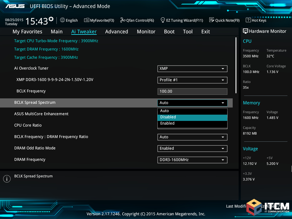
FCC certification testing is often completed with the spread-spectrum function enabled in order to reduce the measured emissions to within acceptable legal limits. However, the spread-spectrum functionality may be disabled by the user in some cases. As an example, in the area of personal computers, some BIOS writers include the ability to disable spread-spectrum clock generation as a user setting, thereby defeating the object of the EMI regulations. This might be considered a loophole , but is generally overlooked as long as spread-spectrum is enabled by default.
Ssbbw Sperm
Free Youporn
Girl In Lingerie Solo
Miss Pageant Nudist Torrent
Ride Him Porn