Backpage Mpls Mn

⚡ 👉🏻👉🏻👉🏻 INFORMATION AVAILABLE CLICK HERE 👈🏻👈🏻👈🏻
MPLS (Multiprotocol label switching) является протоколом для ускорения и формирования потоков сетевого трафика, что, по сути, означает сортировку MPLS и расстановку приоритетов в ваших пакетах данных на основе их класс обслуживания (например, IP-телефон, видео или данные Skype). При использовании протоколов MPLS доступная используемая пропускная способность увеличивается, а критически важные приложения, такие как передача голоса и видео, гарантируют 100% бесперебойную работу.
MPLS это метод маркировки пакетов, который устанавливает приоритетность данных. Большинство соединений сети должны анализировать каждый пакет данных на каждом маршрутизаторе, чтобы точно понимать его маршрут следования.
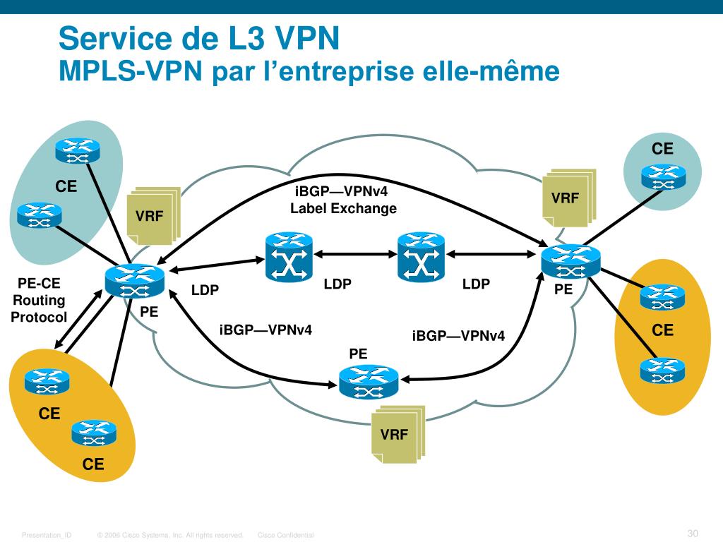
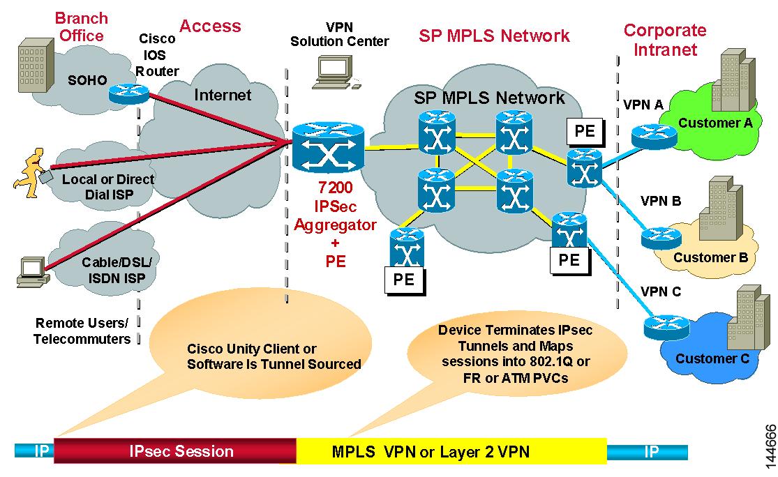
CE маршрутизатор, используемый со стороны узла клиента, который непосредственно подключается к маршрутизатору оператора.
CE взаимодействует с маршрутизатором со стороны оператора (PE) и обменивается маршрутами внутри PE. Используемый протокол маршрутизации может быть статическим или динамическим (протокол внутреннего шлюза, такой как OSPF, или протокол внешнего шлюза, такой как BGP).
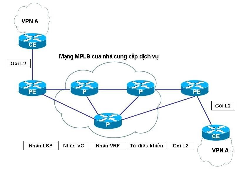
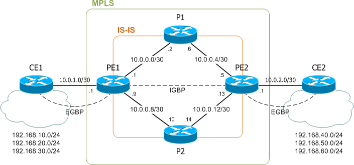
Раскроем не понятные аббревиатуры - маршрутизатор Customer Edge (CE) подключается к маршрутизатору Provider Edge (PE).
PE маршрутизатор - граничный маршрутизатор со стороны оператора (MPLS домена), к которому подключаются устройства CE. Приставка PE к маршрутизатору, означает то, что он охватывает оборудование, способное к работе с широким диапазоном протоколов маршрутизации, в частности:
Некоторые маршрутизаторы PE также выполняют маркировку трафика.
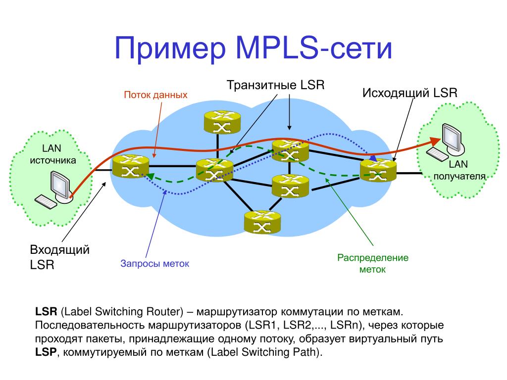
P - маршрутизатор - внутренний маршрутизатор сети оператора (провайдера) MPLS домена. В многопротокольной коммутации по меткам (MPLS) маршрутизатор P функционирует как транзитный маршрутизатор базовой сети. Маршрутизатор P обычно подключен к одному или нескольким маршрутизаторам PE.
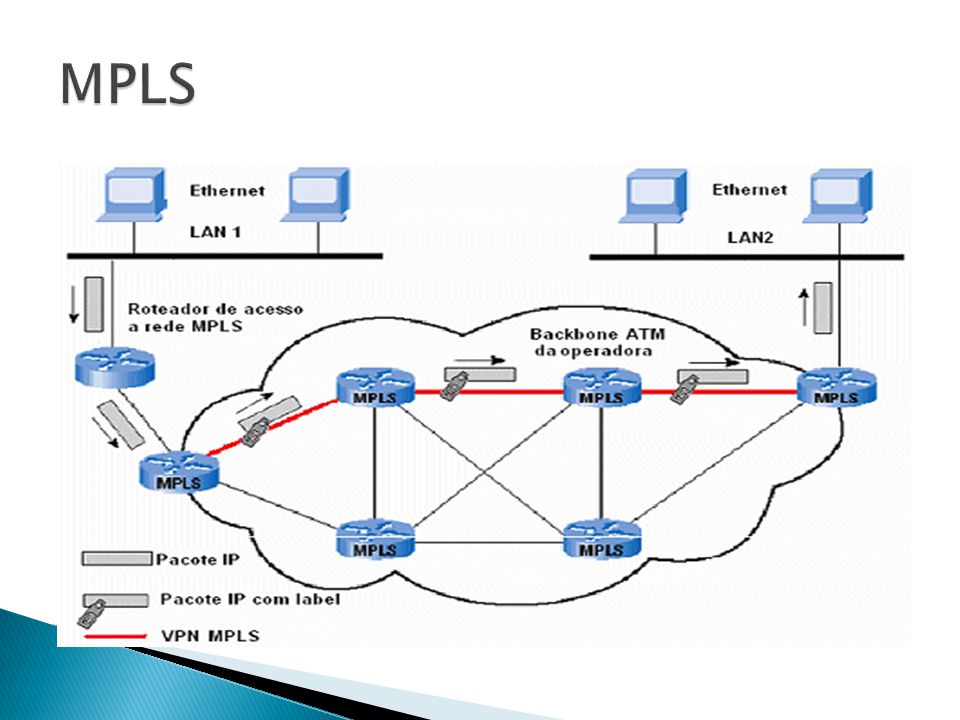
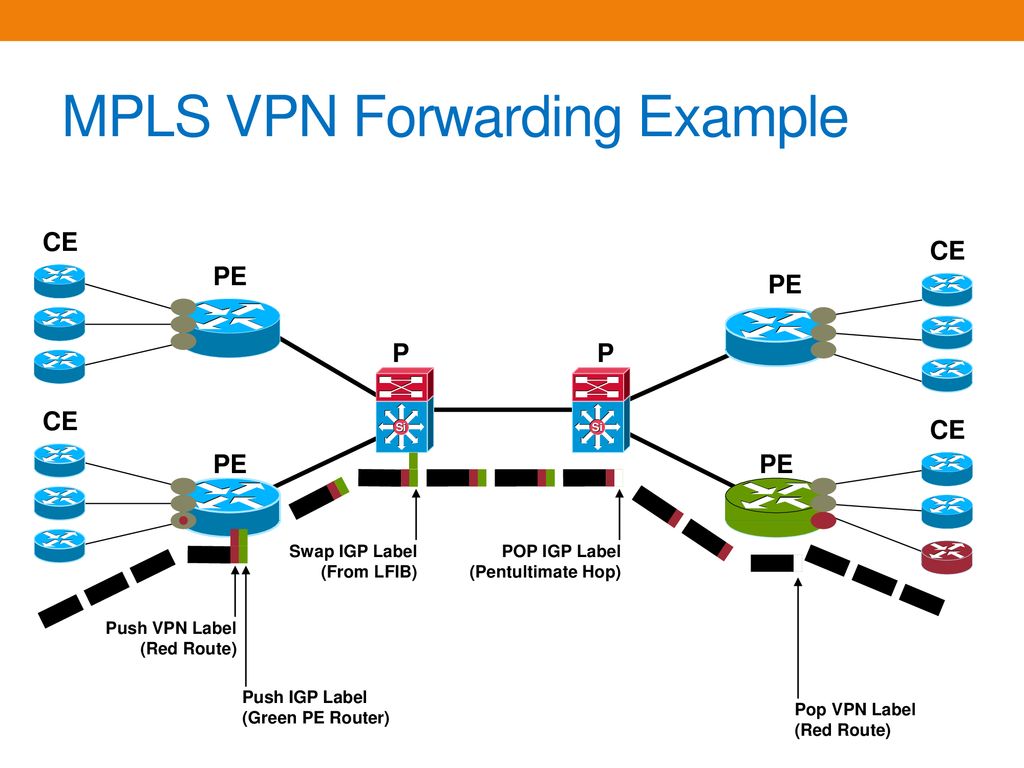
Входной маршрутизатор с MPLS (напомним, multiprotocol label switching, с английского) будет помечать пакеты данных при входе в сеть расставляя метки, поэтому, маршрутизаторы будут точно понимать, куда направляются данные, без необходимости снова и снова анализировать пакет с данными.
Чтобы понять принцип работы методики MPLS следует отметить, что в традиционной IP-сети каждому маршрутизатору приходится выполнять поиск IP, путем постоянного поиска его в таблицах с пакетами данных с последующей пересылкой на следующий уровень пока пакеты данных не достигнут нужного пункта назначения.
MPLS технология присваивает метку всем IP-пакетам, а тем временем уже сами маршрутизаторы принимают решение о передаче пакета далее на следующее устройство благодаря нужному значению метки. Метка добавляется в составе MPLS заголовка, который добавляется между заголовком кадра (второй уровень OSI) и заголовком пакета (третий уровень OSI) и, по сути, в дальнейшем идет их наложение друг на друга.
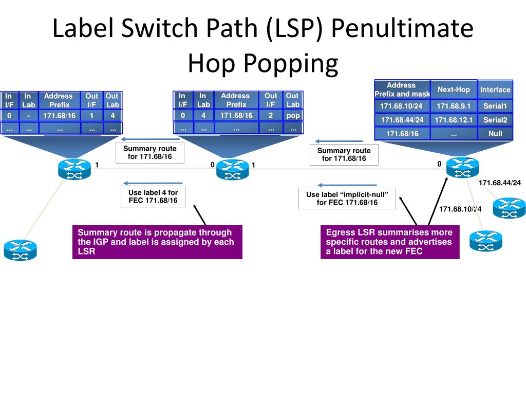
Методика MPLS вместо этого выполняет "коммутацию меток", когда первое устройство выполняет поиск маршрутизации, как и прежде, но вместо поиска следующего перехода он находит конечный маршрутизатор назначения по заранее заданному маршруту. Маршрутизатор определяет метку на основе информации, которую будут использовать маршрутизаторы для дальнейшей маршрутизации трафика без необходимости каких-либо дополнительных поисков IP адресов, по достижению конечного маршрутизатора метка удаляется и пакет доставляется с помощью обычной IP маршрутизацией.
Для работы MPLS используют протоколы маршрутизации распространения меток (LDP), простой неограниченный протокол (без поддержки трафика), протокол резервирования ресурсов с проектированием трафика (RSVP-TE). На практике же обычно используют протокол распространения меток (LDP), однако протокол RSVP-TE необходим для функций организации трафика и в сложных сетях фактически не обойтись без этих двух протоколов с настройкой LDP для туннелирования внутри протокола RSVP.
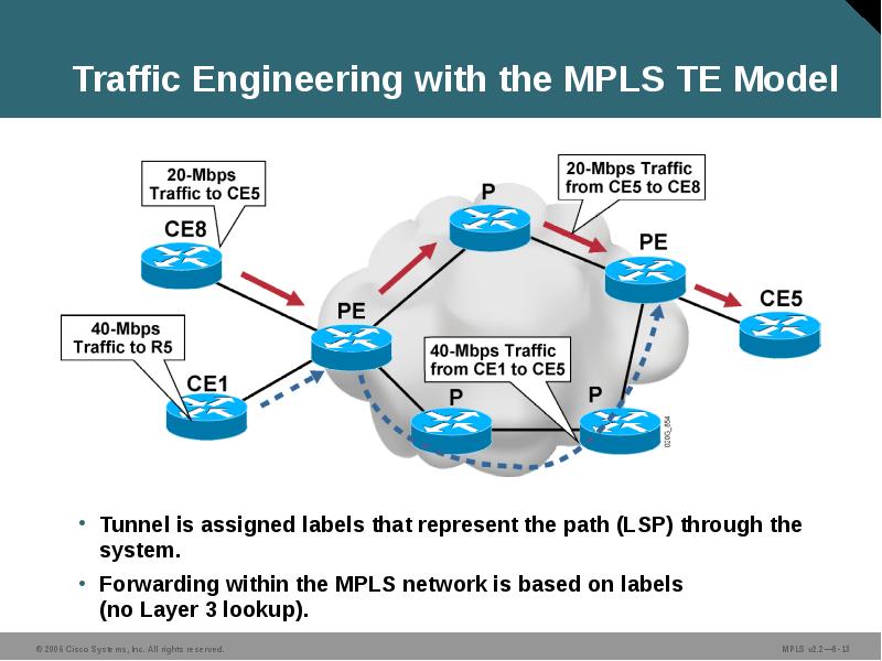
Передача и управление трафиков происходит за счёт технологии Traffic Engineering, которая осуществляет передачу трафика по каналам по наиболее оптимальному маршруту, но с некоторыми ограничениями благодаря технологии CSPF (Constrained Shortest Path First), которая выбирает пути не только пользуясь критерием, основанном на его оптимальной длине маршрута, но еще и учитывает загрузку маршрутов. Используемые протоколы RSVP-TE позволяют резервировать полосы пропускания в сети.
Технология MPLS также имеет защиту от сбоев основываясь предварительном расчете путей резервного копирования для потенциальных сбоев канала или узла. При наличии сбоя в сети автоматически происходит расчет наилучшего пути, но при наличии одного сбоя расчет необходимого пути начинает происходить еще до обнаружения сбоя. Пути резервного копирования предварительно запрограммированы в FIB маршрутизатора в ожидании активации, которая может произойти в миллисекундах после обнаружения сбоя.
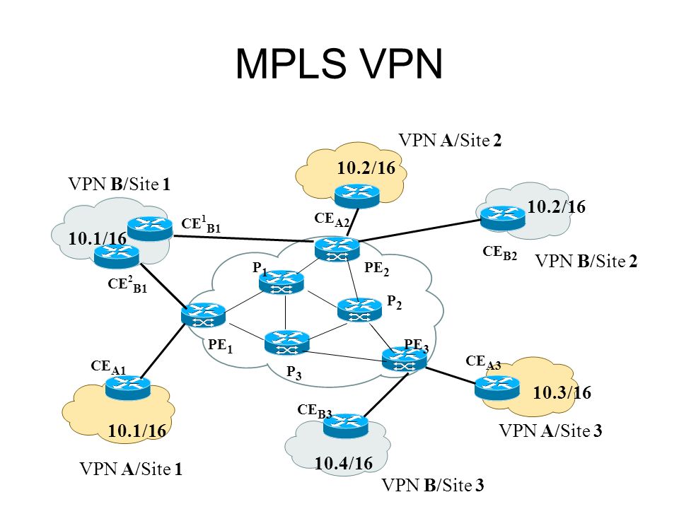
В заключении следует отметить, что на практике MPLS в основном используется для пересылки единиц данных протокола IP (PDU, (Protocol Data Unit)) и трафика виртуальной частной локальной сети (VPLS) Ethernet. Основными приложениями MPLS являются инженерия телекоммуникационного трафика и MPLS VPN.
— Узнать IP - адрес компьютера в интернете
— Онлайн генератор устойчивых паролей
— Калькулятор инсталляции IP - АТС Asterisk
— Руководство администратора FreePBX на русском языке
— Руководство администратора Cisco UCM/CME на русском языке
— Руководство администратора по Linux/Unix
Products Support & Learn Partners Events & Videos
Back
Africa French - Français
Africa Portuguese - Português
Argentina - Español
Australia & New Zealand - English
Austria - Deutsch
Belgium & Luxembourg - English • Français • Nederlands
Bolivia - Español
Brazil - Português
Canada - English • Français
Chile - Español
Colombia - Español
Costa Rica - Español
Czech Republic - Czech
Denmark - Dansk
East Africa - English
Ecuador - Español
Egypt - English • عربي
El Salvador - Español
France - Français
Germany - Deutsch
Guatemala - Español
Honduras - Español
Hong Kong - English • 繁體中文
Hungary - Magyar
India - English
Indonesia - English
Israel - English
Italy - Italiano
Japan - 日本語
Korea - 한국어
Mainland China - 简体中文
Malaysia - English
Mexico - Español
Middle East - English • عربي
Netherlands - Nederlands
Nicaragua - Español
North Africa - عربي
Norway - Norsk
Panama - Español
Paraguay - Español
Peru - Español
Philippines - English
Poland - Polski
Portugal - Português
Puerto Rico - Español
Romania - România
Russia - Русский
Singapore - English
South Africa - English
Spain - Español
Sweden - Svenska
Switzerland - Français • Deutsch
Taiwan - 繁體中文
Thailand - ภาษาไทย
The Caribbean - Español
Turkey - Türkiye
Ukraine - Українська • Російська
United Kingdom & Ireland - English
United States - English
Uruguay - Español
Venezuela - Español
Vietnam - Việt
West Africa - English
Back
Canada - English • Français
United States - English
Back
Africa French - Français
Africa Portuguese - Português
Egypt - English • عربي
East Africa - English
North Africa - عربي
South Africa - English
West Africa - English
Back
Australia & New Zealand - English
India - English
Indonesia - English
Japan - 日本語
Korea - 한국어
Malaysia - English
Philippines - English
Singapore - English
Thailand - ภาษาไทย
Vietnam - Việt
Back
Austria - Deutsch
Belgium & Luxembourg - English • Français • Nederlands
Czech Republic - Czech
Denmark - Dansk
France - Français
Germany - Deutsch
Hungary - Magyar
Israel - English
Italy - Italiano
Netherlands - Nederlands
Norway - Norsk
Poland - Polski
Portugal - Português
Romania - România
Russia - Русский
Spain - Español
Sweden - Svenska
Switzerland - Français • Deutsch
Turkey - Türkiye
Ukraine - Українська • Російська
United Kingdom & Ireland - English
Back
Mainland China - 简体中文
Hong Kong - English • 繁體中文
Taiwan - 繁體中文
Back
Argentina - Español
Brazil - Português
Bolivia - Español
Chile - Español
Colombia - Español
Costa Rica - Español
Ecuador - Español
El Salvador - Español
Guatemala - Español
Honduras - Español
Mexico - Español
Nicaragua - Español
Panama - Español
Paraguay - Español
Peru - Español
Puerto Rico - Español
The Caribbean - Español
Uruguay - Español
Venezuela - Español
This document describes Unified Multiprotocol Label Switching (MPLS), which is all about scaling. It provides a framework of technology solutions to bring simple end-to-end traffic and/or services across a traditionally segmented infrastructure. It makes use of both the benefits of a hierarchical infrastructure as it improves scalability and the simplicity of network design.
There are no specific requirements for this document.
This document is not restricted to specific software and hardware versions.
The information in this document was created from the devices in a specific lab environment. All of the devices used in this document started with a cleared (default) configuration. If your network is live, make sure that you understand the potential impact of any command.
When you look at the history of the network packet-based services, then a change in network business values can be observed. This goes from discrete connectivity enhancements in order to make applications as fluent as possible, to collaboration technologies in order to support mobile collaboration. Finally, the on-demand cloud services are introduced with the application services in order to optimize the tools used with an organization and improve stability and cost-of-ownership.
This continuous value and functionality enhancement of the network results in a much more pervasive need for network simplicity, manageability, integration, and stability where networks have been segmented as a result of disjointed operational islands and no real end-to-end path control. Now there is a need to bring it all together with a single architecture which is easy to manage, provides scalability to 100,000's of nodes, and uses the current High Availability and Fast Convergence technologies. This is what Unified MPLS brings to the table, which is the segmented network into a single control plane and end-to-end path visibility.
How can you simplify MPLS operations in increasingly larger networks with more complex application requirements?
Traditional MPLS Challenges with Different Access Technologies
The Unified MPLS attraction is summarized in this list:
Unified MPLS is defined by the addition of extra features with classical/traditional MPLS and it gives more scalability, security, simplicity and manageability. In order to deliver the MPLS services end-to-end, end-to-end Labeled Switches Path (LSP) is needed. The goal is to keep the MPLS services (MPLS VPN, MPLS L2VPN) as they are, but introduce greater scalability. In order to do this, move some of the IGP prefixes into Border Gateway Protocol (BGP) (the loopback prefixes of the Provider Edge (PE) routers), which then distributes the prefixes end-to-end.
Before the Cisco Unified MPLS architecture is discussed, it is important to understand the key features used in order to make this a reality.
It is a prerequisite to have a scalable method in order to exchange prefixes between network segments. You could simply merge the IGPs (Open Shortest Path First (OSPF), Intermediate System-to-Intermediate System (IS-IS), or Enhanced Interior Gateway Routing Protocol (EIGRP)) into a single domain. However an IGP is not designed to carry 100,000s of prefixes. The protocol of choice for that purpose is BGP. It is a well-proven protocol which supports the Internet with 100,000's of routes and MPLS-VPN environments with millions of entries. Cisco Unified MPLS uses BGP-4 with label information exchange (RFC3107). When BGP distributes a route, it can also distribute an MPLS label that is mapped to that route. The MPLS label mapping information for the route is carried in the BGP update message that contains the information about the route. If the next hop is not changed, the label is preserved and the label changes if the next hop changes. In Unified MPLS, the next hop changes at Area Border Routers (ABRs).
When you enable RFC 3107 on both BGP routers, the routers advertise to each other that they can then send MPLS labels with the routes. If the routers successfully negotiate their ability to send MPLS labels, the routers add MPLS labels to all outgoing BGP updates.
The label exchange is needed in order to keep the end-to-end path information between segments. As a result, each segment becomes small enough to be managed by operators and at the same time there is circuit information distributed for path awareness between two different IP speakers.
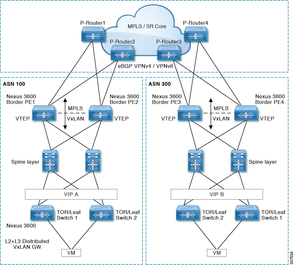
In Figure 3 you can see that there are three segments with Label Discovery Protocol Labeled Switches Path (LDP LSP) and the access network does not have LDP enabled. The objective is to join them together so that there is a single MPLS path (Internal BGP (iBGP) hierarchal LSP) between Pre-Aggregation (Pre-Agg) Nodes. As the network is a single BGP Autonomous System (AS), all sessions are iBGP sessions. Each segment runs its own IGP (OSPF, IS-IS,or EIGRP) and LDP LSP paths within the IGP domain. Within Cisco Unified MPLS, the routers (ABRs) that join the segments must be BGP inline route-reflectors with the Next-Hop-Self and RFC 3107 in order to carry a IPv4 + Label configured on the sessions. These BGP speakers are within the Cisco Unified MPLS Architecture referenced to as ABRs.
Why are the ABRs inline route-reflectors?
One of the goals of Unified MPLS is to have a highly scalable end-to-end infrastructure. Thus, each segment should be kept simple in order to operate. All peerings are iBGP peerings, therefore there is a need for a full-mesh of peerings between all iBGP speakers within the complete network. That results in a very impractical network environment if there are thousands of BGP speakers. If the ABRs are made route-reflectors, the number of iBGP peering is reduced to the number of BGP speakers 'per-segment' instead of between 'all' BGP speakers of the complete AS.
BGP operates on the base of recursive routing lookups. This is done in order to accommodate scalability within the underlying IGP that is utilized. For the recursive lookup, BGP uses Next-Hop attached to each BGP route entry. Thus, for example, if a Source-Node desires to send a packet to a Destination-Node and if the packet hits the BGP router, then the BGP router does a routing lookup in its BGP routing table. It finds a route toward Destination-Node and finds the Next-Hop as a next step. This Next-Hop must be known by the underlying IGP. As the final step, the BGP router forwards the packet onwards based upon the IP and MPLS label information attached to that Next-Hop.
In order to make sure that within each segment only the Next-Hops are needed to be known by the IGP, it is needed that the Next-Hop attached to the BGP entry is within the network segment and not within a neighbor or further away segment. If you rewrite the BGP Next-Hop with the Next-Hop-Self feature, ensure that the Next-Hop is within the local segment.
Figure 4 provides an example of how the L3 VPN prefix 'A' and label exchange operates and how the MPLS label stack is created to have the end-to-end path information for the traffic flow between both PEs.
The network is partitioned as three independent IGP/LDP domains. The reduced size of routing and forwarding tables on the routers is to enable better stability and faster convergence. LDP is used to build intradomain LSPs within domains. RFC 3107 BGP IPv4+ labels are used as interdomain label distribution protocol in order to build hierarchical BGP LSPs across domains. BGP3107 inserts one extra label in the forwarding label stack in the Unified MPLS architecture.
VPN Prefix 'A' is advertised by PE31 to PE11 with L3VPN service label 30 and next hop as PE31's loopback via end-to-end interdomain hierarchical BGP LSP. Now, look at the forwarding path for VPN prefix 'A' from PE11 to PE31.
When you look at the MPLS label stack, the switching of the packet between a source and destination device based upon the previous prefix and label exchange is observed within the MPLS switching environment.
This is a Cisco technology which is used in BGP failure scenarios. The network converges without a loss of the traditional seconds in the BGP reconvergence. When BGP PIC is used, most failure scenarios can be reduced to a reconvergence time below 100 msec.
Traditionally when BGP detects a failure, it recalculates for each BGP entry for the best path. When there is a routing table with thousands of route entries, this can take a considerable amount of time. In addition, this BGP router needs to distribute all those new best paths to each of its neighbors in order to inform them of the changed network topology and the changed best-paths. As the final step, each of the recipient BGP speakers needs to make a best path calculation in order to find the new best paths.
Every time the first BGP speaker detects something wrong, it starts the best path calculation until all of its neighbor BGP speakers have done their recalculation, the traffic flow might be dropped.
The BGP PIC for IP and MPLS VPN feature improves BGP convergence after a network failure. This convergence is applicable to both core and edge failures and can be used in both IP and MPLS networks. The BGP PIC for IP and the MPLS VPN feature creates and stores a backup/alternate path in the routing information base (RIB), forwarding information base (FIB), and Cisco Express Forwarding (CEF) so that when a failure is detected, the backup/alternate path can immediately take over, thus it enables fast failover.
With a single rewrite of the next-hop information the traffic flow is restored. Additionally the network BGP convergence happens in the background, but the traffic flows are not impacted anymore. This rewrite happens within 50 msec. If you use this technology, network convergence is reduced to from seconds to 50 msec plus the IGP convergence.
BGP Add-Path is an improvement on how BGP entries are communicated between BGP speakers. If on a certain BGP speaker there is more than a single entry towards a certain destination, then that BGP speaker only sends the entry which is its best path for that destination to its neighbors. The result is that no provisions are made in order to allow the advertisement of multiple paths for the same destination.
BGP Add-Path is a BGP feature to allow more as only the best path, and allows multiple paths for the same destination without the new paths implicitly replacing any previous ones. This extension to BGP is particularly important in order to aid with BGP PIC, when BGP route-reflectors are used, so that the different BGP speakers within an AS have access to more BGP paths as just the 'Best BGP path' in accordance with the route-reflector.
Operations to achieve 50-millisecond restoration after a link or node failure can be simplified dramatically with the introduction of a new technology called loop-free alternates (LFAs). LFA enhance the link-state routing protocols (IS-IS and OSPF) in order to find alternative routing paths in a loop-free manner. LFA allows each router to define and use a predetermined backup path if an adjacency (network node or link) fails. In order to deliver a 50 msec restoration time in case of link or node failures, MPLS TE FRR can be deployed. However, this requires the addition of another protocol (Resource Reservation Protocol, or RSVP) for setup and management of TE tunnels. While this might be necessary for bandwidth management, the protection and restoration operation does not require bandwidth management. Hence, the overhead associated with the addition of RSVP TE is considered high for simple protection of links and nodes.
LFA can provide a simple and easy technique without the deployment of RSVP TE in such scenarios. As a result of these techniques, today's interconnected routers in large-scale networks can deliver 50 msec restoration for link and node failures without a configuration requirement for the
Сети для самых маленьких. Часть десятая. Базовый MPLS / linkmeup
MPLS - как работает и зачем нужен? | База знаний - Мерион Нетворкс
Unified MPLS Functionality, Features, and Configuration Example - Cisco
Сети для самых маленьких. Выпуск десятый. Базовый MPLS - YouTube
MPLS — Википедия
Executive Escorts
Ebony Escorts Florida
Backpage Handjob
Backpage Mpls Mn