2 Liter Bottle Insertion

👉🏻👉🏻👉🏻 ALL INFORMATION CLICK HERE 👈🏻👈🏻👈🏻
From Wikipedia, the free encyclopedia
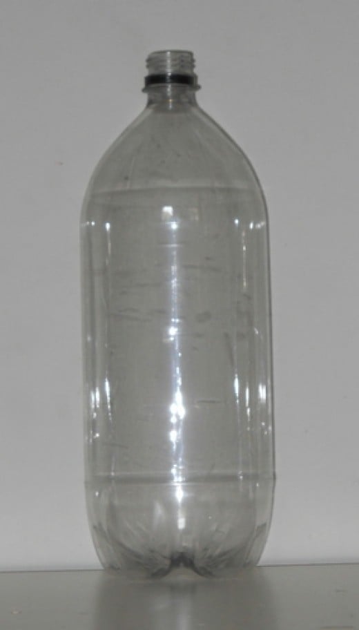
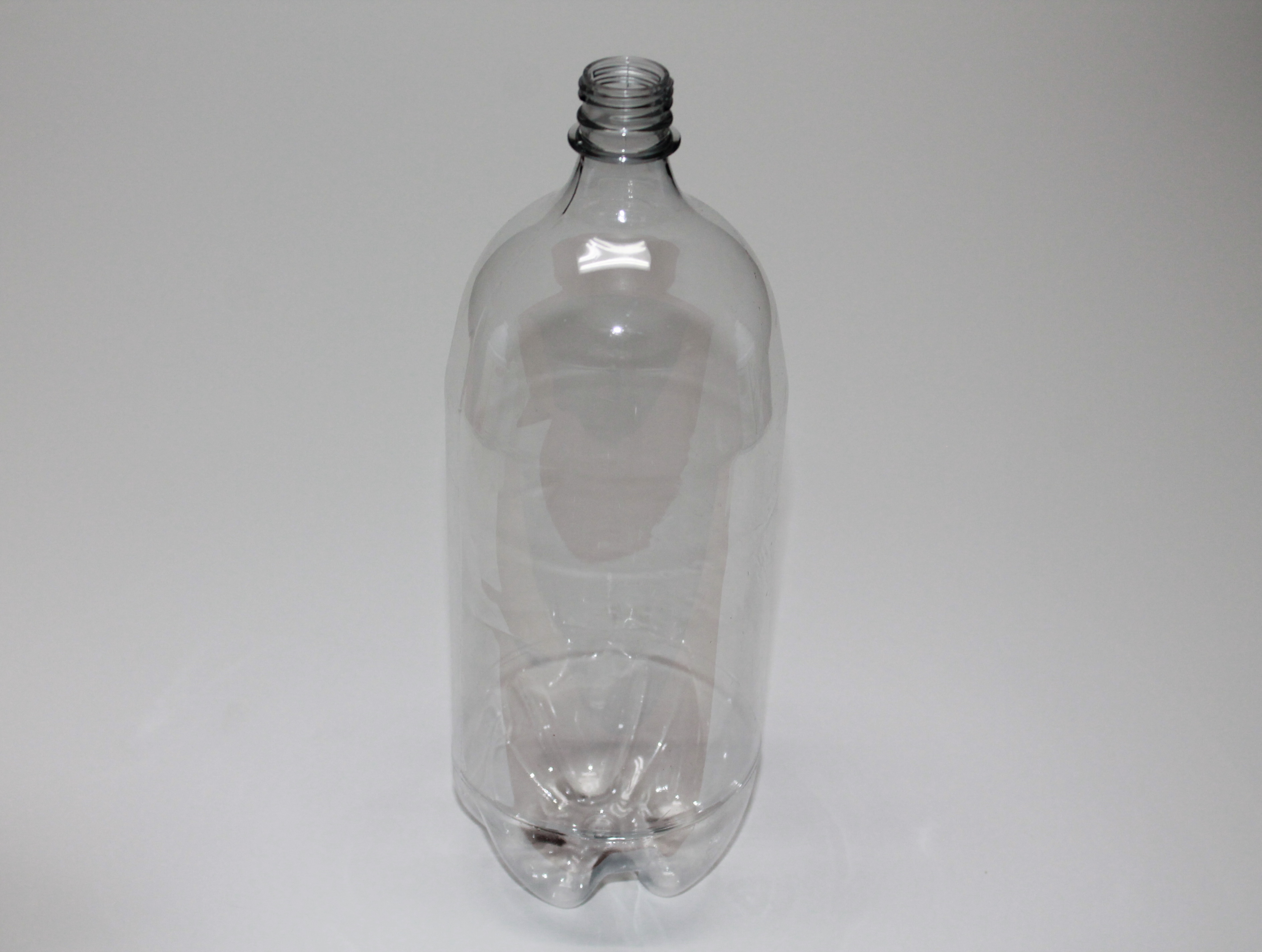
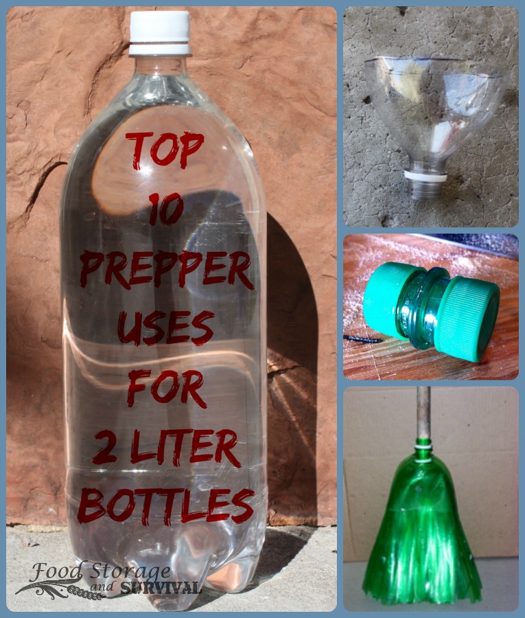
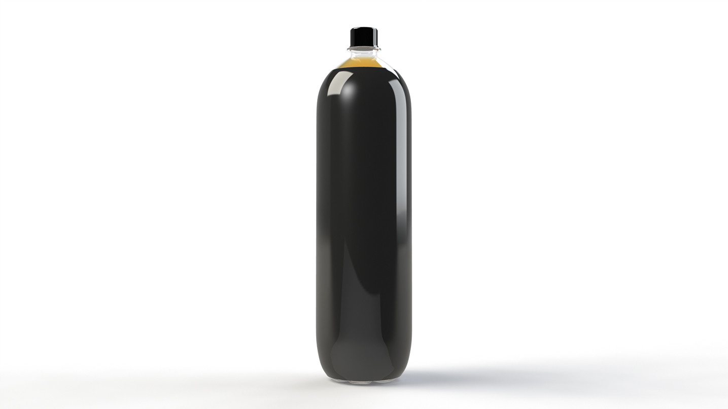
The two-liter bottle is a common container for soft drinks, beer, and wine. These bottles are produced from polyethylene terephthalate, also known as PET plastic, or glass using the blow molding process. Bottle labels consist of a printed, tight-fitted plastic sleeve. A resealable screw-top allows the contents to be used at various times while retaining carbonation.
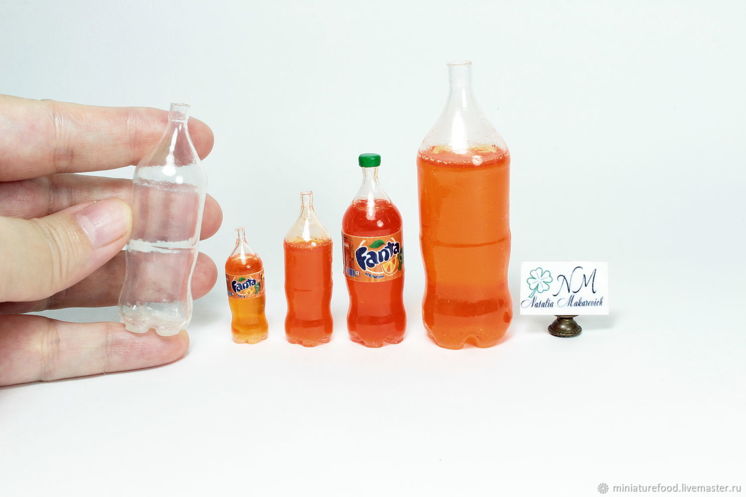
In the United States, the two-liter bottle is one of the few cases where a product is sold by a round number of metric units. Since very few other beverages are sold in this exact quantity, the term "two-liter" in American English almost invariably refers to a soft drink bottle. Other common metric sizes for plastic soft drink bottles include 500 milliliters, 1 liter, and 3 liters.
PepsiCo introduced the first two-liter sized soft drink bottle in 1970.[1] Motivated by market research conducted by new marketing vice president John Sculley (who would later be known for heading Apple Inc. from 1983 to 1993),[2] the bottle and the method of its production were designed by a team led by Nathaniel Wyeth of DuPont, who received the patent in 1973.[3] In 1985, a three-liter bottle appeared on supermarket shelves. The design is still used to this day by some bottlers.[4][5]
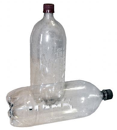
Most modern-day two-liter bottles are one piece of PET (polyethylene terephthalate) with a base that is molded with a radial corrugation to provide strength for the bottom and the ability to stand upright. Most early two-liters had a separate opaque base glued to the hemispherical bottom of the clear PET flask. This base had a coaxial corrugation and drain holes. It was abolished in the 1990s, in part due to difficulties recycling the two separate plastics.[citation needed]
Used two-liter bottles see new life in a variety of uses including carpeting, boat hulls, polyester fabric, filling for jackets, sleeping bags, mattresses, pillows, recycling bins, scouring pads, and, on an increasing scale, new soft drink bottles.[6]
Disclaimer: This “Instructable” is provided “As Is” without any express or implied warranty of any kind including warranties of merchantability, noninfringement, or fitness for a particular purpose. The Author of this “Instructable” does not warrant or assume responsibility for the accuracy or completeness of any information, text, graphics, links or other items contained within this “Instructable” post. In no event shall the Author of this “Instructable” be liable for any damages whatsoever (including, without limitation, lost profits, business interruption, lost information, damaged electronic equipment and circuits, damage to property) or be liable for any personal harm / pleasure / death whatsoever (including intentional or unintentional, without limitation, cuts, scratches, lacerations, punctures, bruises, inhalation, swallowing, or insertions) arising out of the use of or inability to use this “Instructable”, even if the Author of this “Instructable” has been advised of the possibility of such damages or personal risks.
In short... Do your own engineering work and analysis of the approach for your specific implementation to determine validity, safety, and assume accountability for the outcome of your engineering assessment; assess and mitigate the risks specific to your scenario and skill level. Use good sense on how, where, and if to use this approach; if you are unsure, do not use it... I would have said common sense, but common sense is definitely not common.
Items: Rubber Stopper, #3, 1-hole – Quantity 1
Items: 2” Long .453 inch wheel diameter (TR Valve Number 418) Tire Value – Quantity 1
Item: Pressure Treated Lumber 2X4X16 inches – Quantity 1
Item: Pressure Treated Lumber 4X4X16 inches – Quantity 2
Item: 1-1/4 inch x 8 inch Punched Angle – Quantity 2
Item: 4 Inch Adjustable Spring Hinge – Quantity 2
Item: 1/4 inch - 20 X 3/4 inch Machine Screw with Nuts – Quantity 4
Item: 1/4 inch - 20 X 2 inch Machine Screw with Nuts – Quantity 4
Item: 1/4 inch Flat Washer – Quantity 8
Item: 1/4 inch Split Washer – Quantity 8
Item: 2-1/2 inch Deck Screws – Quantity 4
Item: Velcro 23 inch X 7/8 in with Hook and Loop – Quantity 1
Item: #18 Twisted Mason Line (~25 feet) – Quantity 1
Item: 3/8 inch Vinyl Bumpers – Quantity 6
Clarification: Any factory bicycle pump will work for this project; however, since I wanted to extend the distance between the bicycle pump and launcher for added safety, I decided to modify one. Here is the configuration I used to extend the hose distance of the bicycle pump.
Item: Bell Air Attack 300 Air Pump - Quantity 1
Item: 1/4 inch PP Standard Check Valve - Quantity 1
Item: 3/8 inch X 1/4 inch X 20 feet Clear Vinyl Tube (rated 55psi @ 70F /20C) - Quantity 1
Item: 3/4 inch Electrical Tape - Quantity ~3 inches
With Rubber Stopper snuggly secured in a vice, widen existing hole in #3 Rubber Stopper using 3/8 inch bit and an Electric Drill. It is important to not over widen the Rubber Stopper hole.
Insert Tire Value into the #3 Rubber Stopper so that the Schrader Value will protrude on the wider end of the #3 Rubber Stopper. I found that rubbing a little liquid dish soap on the value and “persuading” it with a Rubber Malt helps with the insertion process.
Using a Hack Saw, cut 1-1/4 inch Punched Angle to two 8 inch lengths. Ensure you remove all the rough and sharp edges with a metal file to reduce risks of being cut.
Using a 1/4 inch X 3/4 inch Machine Screw, 1/4 inch flat washer, 1/4 inch split washer, and 1/4 inch nut combination, affix the Punched Angle to the 4 inch hinge using the two outer hinge screw holes ensuring the Punched Angle is centered to the hinge. Do this for both hinges ensuring a mirror configuration of the Punched Angle to the hinge.
Cut one 2X4 Pressure Treated Lumber to 16 inches long; this will become the Launch Pad Base.
Cut two 4X4 Pressure Treated Lumber to 16 inches long; this will become the Launch Pad stabilization feet.
Identify center point of Launch Pad Base Pressure Treated Lumber and mark with pencil.
Drill a small pilot hole (~3/32 inch bit) into the center point of Launch Pad Base (2X4X16 Pressure Treated Lumber) ensuring pilot hole goes completely through.
Drill 1 inch hole centered on pilot hole ~1/8 inch deep using Spade or Forstner bit into the top of the Launch Pad Base; this is to start the Pressurization Plug Housing hole enough so that you can continue to remove move material during a future step.
Drill 1-5/8 inch hole centered on pilot hole ~1/8 inch deep using Spade or Forstner bit into the bottom of the Launch Pad Base; this is to start the Bicycle Pump Hose Head hole enough so that you can continue to remove move material later during a future step.
Drill out completely the initial Launch Pad Base center pilot hole with a 3/8 inch bit.
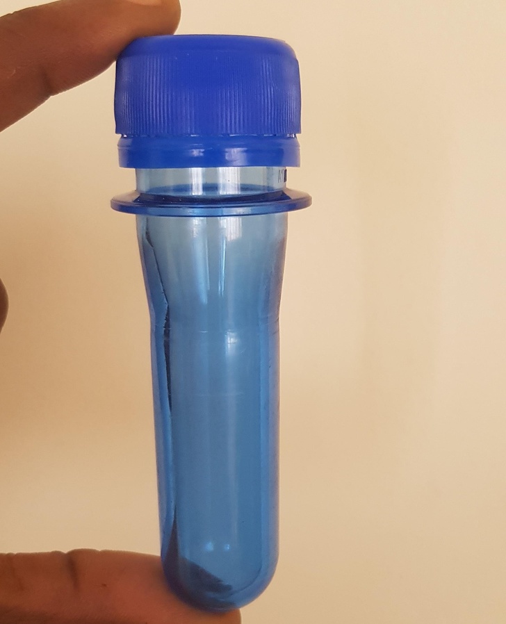
Take the Pressurization Plug and insert it into the 2 Liter Bottle; do not over penetrate the plug into 2 Liter Bottle pour nozzle. In my trials, the Pressurization Plug Rubber should penetrate about 3/8 inch into the 2 Liter Bottle pour nozzle.
Place assembled Pressurization Plug and 2 Liter Bottle into the drilled out 1 inch Pressurization Plug Housing hole on top of the Launch Pad Base.
Unfold and align the Launch Pad Clamp assemble (hinge and angle metal) so that the lip of the Launch Pad Clamp is on top of the 2 Liter Bottle neck rim and flush to the 2 Liter Bottle neck.
The Launch Pad Clamp should be perpendicular to the 2 Liter Bottle when positioned over the 2 Liter Bottle neck rim; if not, carefully remove additional material from the Pressurization Plug Housing hole with the 1 inch Spade or Forstner bit until perpendicular alignment is obtained.
Note: I found that drilling out ~7/16 inch of material is usually the right amount; however, I would recommend taking the time to fine tune the depth of the Pressurization Plug Housing for your build. Also note that not all 2 Liter Soda Bottle are the same and there may be small variation between soda manufactures and brands.
With the Pressurization Plug still inserted into housing (it does not need to be attached to the 2 Liter Bottle), turn Launch Pad Base over, and note the amount of material that needs to be removed from the bottom of the Launch Pad Base to have the Pressurization Plug Schrader Value protruding completely so that the Bicycle Pump Hose Head can be secured properly. Using a 1-5/8 inch Spade or Forstner bit and electric drill, remove the necessary material. You should be able to clasp the Bicycle Pump Hose Head completely onto the Pressurization Plug Schrader Value.
With the assembled Pressurization Plug and 2 Liter bottle assemble in the “tuned” Pressurization Plug Housing (ensuring a perpendicular position to the Launch Pad base), tightly butt up both Launch Pad Clamps halves to the 2 Liter Bottle.
While ensuring the Launch Pad Clamps halves are centered on the Launch Pad base, mark drill holes for the two inner holes of both hinges on the Launch Pad Base.
Drill a small pilot hole (~3/32 inch bit) into each of the marked Launch Pad Base hinge holes ensuring pilot hole goes completely through.
Drill 1/2 inch hole ~1/4 inch deep using Spade or Forstner bit into the bottom of the Launch Pad Base where the four hinge pilot holes punched through.
Drill out completely the four initial hinge pilot holes with a 1/4 inch bit.
Using a 1/4 inch X 2 inch Machine Screw, 1/4 inch flat washer, 1/4 inch split washer, and 1/4 inch nut combination, thread machine screws through Launch Pad Clamp Hinge to Launch Pad Base.
Using a Philip Screw Driver and Socket Ratchet, tighten all four machine screws. Do not over tighten to the point the hinge does not swing relatively freely.
Using Vinyl Bumpers, remove the adhesive backing and place 3 bumpers strategically around on the inner bottom hinge plate on both Launch Pad Clamp halves; this is used to damper the return spring force of the Launch Pad Clamps on release.
Using Allen Wrench provided with the hinge kit, place the Launch Pad Clamp hinge spring under slight tension and insert Pin into Spring Pin Housing. I found that tension on the first setting appears to have sufficient retraction force.
Repeat process on second Launch Pad Clamp hinge.
You should be able to pull the two Launch Pad Clamp halves together, release, and have them snap back down.
Note: Make sure you watch your hands and other body parts; these hinges with the metal brackets come down with force and can cut you badly if not careful.
Center Launch Pad Stabilization Feet (4X4X16 inch Pressured Treated Lumber) underneath the Launch Pad Base so that the Stabilization Foot is perpendicular, centered, and flush to the end of the Launch Pad Base. Fasten with two 2-1/2 inch Deck Screws.
Repeat for other Stabilization Foot on the opposite end of the Launch Pad Base.
Wrap Velcro 23 inch X 7/8 inch strap around one arm of the Launch Pad Clamp ensuring it is feed through the loop end of the Velcro Strap. It is recommended to use the Launch Pad Clamp arm on the opposite side of the Launch Pad Base Bicycle pump head cut out.
Tie #18 Twisted Mason Line to other end of the Velcro strap.
Note: This step is not necessary if you are planning on using an unmodified off the shelf bicycle pump.
Remove Pump Hose from Pump by unscrewing the Hose Nut from the Hose Housing; it may be necessary to use a pair of pliers to loosen the Hose Nut.
Note: When the Pump Hose is removed, the Pump’s Check Value Disc will be free floating; make sure you do not lose it.
Using a pair of Needle Nose Pliers, remove the Check Value Vent from the Pump Hose by gently grasping vent and rocking while prying outward.
Slide off the Pump Hose Nut off Pump Hose.
Note: This step is not necessary if you are planning on using an unmodified off the shelf bicycle pump.
Slide the Pump Hose Nut onto one end of the 3/8 inch X 1/4 inch X 20 feet Clear Vinyl Tube; make sure you orientate the Pump Hose Nut in the right direction.
Insert the extracted Check Value Vent into the end of the 3/8 inch X 1/4 inch Clear Vinyl Tube.
Wrap the end of the 3/8 inch X 1/4 inch Clear Vinyl Tube containing Check Value Vent with about 4 layers of Electrical Tape. Electrical Tape is used to provide additional thickness to the Clear Vinyl Tube so that it seats better in the Hose Housing when the Pump Hose Nut is screwed down.
Insert the Clear Vinyl Tube end with Check Value Vent into the Check Value Hole; ensure that the Pump’s Check Value Disc was still present. Screw down the Pump Hose Nut back onto the Check Value Housing until tight. If you are able to pull up (gently) on the Clear Vinyl Tube and feel it unseat slightly from the Check Value Hole within the Hose Housing, apply an additional layer or two of Electrical Tape on the Clear Vinyl Tube.
Note: This step is not necessary if you are planning on using an unmodified off the shelf bicycle pump.
Insert the 1/4 inch PP Standard Check Valve into the original Bicycle Pump Hose & Head with the valve allowed directional flow towards the Pump Hose Head. If you are unsure which way the Check Value directional flow is, simply try to blowing air through it.
Insert the other end of the 1/4 inch PP Standard Check Value into the free end of the 3/8 inch X 1/4 inch Clear Vinyl Tube.
Note: I did not find it necessary to secure the Clear Vinyl Tube ends with an additional clamps; the barb on the 1/4 inch PP Standard Check Valve seemed to be sufficient.
Place the Launcher Pad on secure footing in an open field or parking lot with a sufficient radius of open space free from building, trees, electrical lines, etc.
Unroll the modified Bicycle Pump Clear Vinyl Tube with the Pump Hose Head within reach of the Launcher Pad Base.
Unroll #18 Twisted Mason Line attached to Velcro strap about 20 feet from Launcher Pad Base.
Fill 2 Liter Bottle with roughly 1/3 (~675ml) to 1/4 (~500ml) full of water and insert Pressurization Plug into 2 Liter Bottle of nozzle.
Turn assembled Pressurization Plug and 2 Liter Bottle upside down and place it into Launch Pad Base Pressurization Plug Housing.
Attach and secure the Bicycle Pump Head to the Pressurization Plug Schrader Value.
Grasp, rotate upward, and hold the Launch Pad Clamp halves so that the lips of both Launch Pad Clamp halves are on top of the 2 Liter Bottle neck rim and flush to the 2 Liter Bottle neck. Make sure you hold Launch Pad Clamps tightly and securely.
Using the Velcro 23 inch X 7/8 inch strap, tightly wrap the Velcro strap over the top of the other Clamp overhang and back underneath onto Velcro’s starting point. Ensure there is enough Velcro overlaps to securely hold the Launch Pad Clamp tension.
Double check to make sure the 2 Liter Bottle and Launch Pad Clamp are secure and also make sure that everyone is clear.
Begin pressurizing the 2 Liter Bottle by pumping the bicycle pump. About 10 good pumps gives a good result; however, experiment with the number of pumps to determine what works well for you.
Note: Too little pressure and the 2 Liter Bottle may not eject the Pressure Plug and not lift off. Too much pressure and the Launch Pad Clamp will slightly give causing Pressure Plug to give, and pressure will release premature or more seriously the 2 Liter Bottle may fail.
When ready to Launch, pull on the #18 Twisted Mason Line “unzipping” the Velcro strap. This will cause the Velcro to pull away allowing the Launch Pad Clamp to retract; once the Launch Pad Clamps retract, the 2 Liter Bottle should have sufficient pressure to eject the Pressure Plug. With the Pressure Plug extracted, the 2 Liter Bottle will thrust pressurized water downward causing the 2 Liter Bottle to lift off.
You are going to want to experiment with different 2 Liter Bottle water and air pressure levels. Roughly 1/3 (~675ml) to 1/4 (~500ml) full of water and 10 good pumps was about sweet spot for me. Too little pressure and the 2 Liter Bottle may not eject the Pressure Plug and not lift off. Too much pressure and the Launch Pad Clamp will slightly give causing pressure to release premature or more seriously the 2 Liter Bottle may fail. If you find yourself where you put too much pressure into the 2 Liter Bottle and it starts to leak from the Pressure Plug, just launch the device as safely and quickly as possible.
I cannot emphasize enough that you need to keep your body parts away from this thing when it is being pressurized, alarmed, or launched. If you are using an unmodified bicycle pump with a short hose, get as far back as you can and make sure your head is not above the 2 Liter Bottle.
If you find yourself in a situation where you inserted too little pressure and the Launch Pad Clamps have been released, just give the Bicycle Pump a couple more pumps; the added pressure should knock the Pressure Plug lose. Do not go over to the Launch Pad and tap the 2 Liter Bottle or Launch Pad Base; you risk knocking it lose and getting pegged with it.
If you feel like pressure is escaping from between Pressure Plug and the 2 Liter Bottle when only moderate pressure exists, either the Launch Pad Clamp is not tight enough and/or the Pressure Plug is not insert far enough. Modified as needed to resolve.
If you believe that you over drilled the Pressure Plug Housing in the Launch Pad Base and that is causing the Pressure Plug to not sit securely against the Launch Pad Base when Launch Pad Clamps are engaged, you can drop a washer or two into the Pressure Plug Housing underneath the Pressure Plug. Just make sure the washer is small enough to fit into the Pressure Plug Housing and the washer has a center hole large enough to allow the Schrader Value to slip through.
If the Velcro strap holding the Launch Pad Clamp together does not release smoothly, double check that you have wrapped the Velcro strap over the top and underneath the Launch Pad Clamp arms allowing the pull of the Twisted Mason Line to back track the Velcro wrap smoothly.
If the Launch Pad Clamp do not release quickly and smoothly, increase the hinge return spring tension. If you accidently lose the Hinge Tension Spring Pin, you can usually use a finishing nail as a suitable replacement.
After initial repeated use, you may find that the through-hole in the Pressure Plug Housing for the Schrader Value may become too tight due to lumber swell from exposure to water. Using a 3/8 inch drill bit, just re-drill it out.
Be Safe and have Fun!!!
--Matt Royer
Did you make this project? Share it with us!
We have a be nice policy.
Please be positive and constructive.
HI is there a chance of making a video it would explain the launch pad a little more better.
Hey Matt, great detailed write up. I work for a middle school and was looking for a bottle rocket laucher and saw this. I liked the simple design. As for the velcro release, maybe use a hitch pin type set up to go through the holes on the angle iron and put a straight cotter pin (teathered to your mason line) to hold it in place. Then, all your pulling and resetting is a cotter pin. (Threaded bolt wih a hole in it might work better. One side mounted with nut, then file down the threads that go through the second). Just my $.02.
Hi, This is a very comprehensive set of build instructions with very good safety notes included. A definate must build for when the grandchildren are next round to stay. I see hours of endless fun for me oops! I mean the grandchildren. As an addition to the projectile construction may I suggest listed in Instructables:-
Water Rocket
by JoeGadget on April 26, 2014
Well done keep the space faring going.
Facebook Twitter Pinterest Google Classroom
2 Liter Bottle Funnel Insert by KristusApollo - Thingiverse
Two -liter bottle - Wikipedia
2 Liter Bottle Water Rocket and Launcher Pad : 15 Steps... - Instructables
2 liter bottle insert in pussy downloadFile name: 2 liter... - Pastebin.com
Find High-Quality 2 liter plastic bottle for Multiple Uses - Alibaba.com
Strapon Porn Sites
Margareth Madè Nude
Brunette Mom Anal
2 Liter Bottle Insertion