POST Power-on Self test
Power-on self-test
This article includes a list of general references, but it lacks sufficient corresponding inline citations. Please help to improve this article by introducingmore precise citations. (October 2010)(Learn how and when to remove this template message)
A power-on self-test (POST) is a process performed by firmware or software routines immediately after a computer or other digital electronic device is powered on.[1]

Typical POST screen. (AMI BIOS)
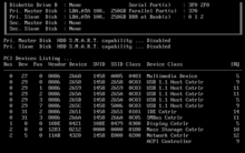
Summary screen after POST and before booting an operating system (AMI BIOS)
This article mainly deals with POSTs on personal computers, but many other embedded systems such as those in major appliances, avionics, communications, or medical equipment also have self-test routines which are automatically invoked at power-on.[2]
The results of the POST may be displayed on a panel that is part of the device, output to an external device, or stored for future retrieval by a diagnostic tool. Since a self-test might detect that the system's usual human-readable display is non-functional, an indicator lamp or a speaker may be provided to show error codes as a sequence of flashes or beeps. In addition to running tests, the POST process may also set the initial state of the device from firmware.
In the case of a computer, the POST routines are part of a device's pre-boot sequence; if they complete successfully, the bootstrap loader code is invoked to load an operating system.
IBM-compatible PC POST
Edit
See also: Booting § Boot sequence of IBM PC compatibles
In IBM PC compatible computers, the main duties of POST are handled by the BIOS/UEFI, which may hand some of these duties to other programs designed to initialize very specific peripheral devices, notably for video and SCSI initialization. These other duty-specific programs are generally known collectively as option ROMs or individually as the video BIOS, SCSI BIOS, etc.
The principal duties of the main BIOS during POST are as follows:
- verify CPU registers
- verify the integrity of the BIOS code itself
- verify some basic components like DMA, timer, interrupt controller
- initialize, size, and verify system main memory
- initialize BIOS
- pass control to other specialized extension BIOSes (if installed)
- identify, organize, and select which devices are available for booting
The functions above are served by the POST in all BIOS versions back to the very first. In later BIOS versions, POST will also:
- initialize chipset
- discover, initialize, and catalog all system buses and devices
- provide a user interface for system's configuration
- construct whatever system environment is required by the target operating system
(In early BIOSes, POST did not organize or select boot devices, it simply identified floppy or hard disks, which the system would try to boot in that order, always.)
The BIOS begins its POST when the CPU is reset. The first memory location the CPU tries to execute is known as the reset vector. In the case of a hard reboot, the northbridge will direct this code fetch (request) to the BIOS located on the system flash memory. For a warm boot, the BIOS will be located in the proper place in RAM and the northbridge will direct the reset vector call to the RAM. (In earlier PC systems, before chipsets were standard, the BIOS ROM would be located at an address range that included the reset vector, and BIOS ran directly out of ROM. This is why the motherboard BIOS ROM is in segment F000 in the conventional memorymap.)
During the POST flow of a contemporary BIOS, one of the first things a BIOS should do is determine the reason it is executing. For a cold boot, for example, it may need to execute all of its functionality. If, however, the system supports power saving or quick boot methods, the BIOS may be able to circumvent the standard POST device discovery, and simply program the devices from a preloaded system device table.
The POST flow for the PC has developed from a very simple, straightforward process to one that is complex and convoluted. During the POST, the BIOS must integrate a plethora of competing, evolving, and even mutually exclusive standards and initiatives for the matrix of hardware and OSes the PC is expected to support, although at most only simple memory tests and the setup screen are displayed.
In earlier BIOSes, up to around the turn of the millennium, the POST would perform a thorough test of all devices, including a complete memory test. This design by IBM was modeled after their larger (e.g. mainframe) systems, which would perform a complete hardware test as part of their cold-start process. As the PC platform evolved into more of a commodity consumer device, the mainframe- and minicomputer-inspired high-reliability features such as parity memory and the thorough memory test in every POST were dropped from most models. The exponential growth of PC memory sizes, driven by the equally exponential drop in memory prices, was also a factor in this, as the duration of a memory test using a given CPU is directly proportional to the memory size.
The original IBM PC could be equipped with as little as 16 KB of RAM and typically had between 64 and 640 KB; depending on the amount of equipped memory, the computer's 4.77 MHz 8088 required between 5 seconds and 1.5 minutes to complete the POST and there was no way to skip it. Beginning with the IBM XT, a memory count was displayed during POST instead of a blank screen.[3] A modern PC with a bus rate of around 1 GHz and a 32-bit bus might be 2000x or even 5000x faster, but it might have more than 3 GB of memory—5000x more. With people being more concerned with boot times now than in the 1980s, the 30- to 60-second memory test adds undesirable delay for a benefit of confidence that is not perceived to be worth that cost by most users. Most clone PC BIOSes allowed the user to skip the POST RAM check by pressing a key, and more modern machines often performed no RAM test at all unless it was enabled via the BIOS setup. In addition, modern DRAM is significantly more reliable than DRAM was in the 1980s.
As part of the starting sequence the POST routines may display a prompt to the user for a key press to access built-in setup functions of the BIOS. This allows the user to set various options particular to the mother board before the operating system is loaded. If no key is pressed, the POST will proceed on to the boot sequence required to load the installed operating system.
Many modern BIOS and UEFI implementations show a manufacturers logo during POST and hide the classic text screens unless an error occurs. The text screen can often be enabled in the BIOS settings by disabling the "Quiet Boot" option.
Progress and error reporting
Edit
BIOS POST card for ISA bus
BIOS POST card for PCI bus.
Professional BIOS POST card for PCI bus.
Two POST seven-segment displays integrated on a computer motherboard
The original IBM BIOS made POST diagnostic information available by outputting a number to I/O port 0x80 (a screen display was not possible with some failure modes). Both progress indication and error codes were generated; in the case of a failure which did not generate a code, the code of the last successful operation was available to aid in diagnosing the problem. Using a logic analyzer or a dedicated POST card—an interface card that shows port 0x80 output on a small display—a technician could determine the origin of the problem. Once an operating system is running on the computer the code displayed by such a board may become meaningless, since some OSes, e.g. Linux, use port 0x80 for I/O timing operations. The actual numeric codes for the possible stages and error conditions differ from one BIOS supplier to another. Codes for different BIOS versions from a single supplier may also vary, although many codes remain unchanged in different versions.
Later BIOSes used a sequence of beeps from the motherboard-attached PC speaker (if present and working) to signal error codes. Some vendors developed proprietary variants or enhancements, such as MSI's D-Bracket. POST beep codes vary from manufacturer to manufacturer.
Information on numeric and beep codes is available from manufacturers of BIOSes and motherboards. There are websites which collect codes for many BIOSes.[4]
Original IBM POST beep codes
Edit
BeepsMeaning1 short beepNormal POST – system is OK2 short beepsPOST error – error code shown on screenNo beepPower supply, system board problem, disconnected CPU, or disconnected speakerContinuous beepPower supply, system board, RAM or keyboard problemRepeating short beepsPower supply, system board or keyboard problem1 long, 1 short beepSystem board problem1 long, 2 short beepsDisplay adapter problem (MDA, CGA)1 long, 3 short beepsEnhanced Graphics Adapterproblem (EGA)3 long beeps3270 keyboard card error
POST AMI BIOS beep codes
Edit
BeepsMeaning1Memory refresh timer error2Parity error in base memory (first 64 KiB block)3Base memory read/write test error4Motherboard timer not operational (check all PSU to MB connectors seated)5Processor failure68042 Gate A20 test error (cannot switch to protected mode)7General exception error (processor exception interrupt error)8Display memory error (system video adapter)9AMI BIOS ROM checksum fix10CMOS shutdown register read/write fix11Cache memory test failedcontinuous beepingMotherboard does not detect a RAM module (continuous beeping)
Reference: "AMIBIOS8 Check Point and Beep Code List Version 2.0 - June 10, 2008"(PDF). Archived from the original (PDF) on 2015-08-07.
POST beep codes on CompTIA A+ certification exam
Edit
These POST beep codes are covered specifically on the CompTIA A+ Exam:
BeepsMeaningSteady, short beepsPower supply may be badLong continuous beep toneMemory failureSteady, long beepsPower supply badNo beepPower supply bad, system not plugged in, or power not turned onNo beepIf everything seems to be functioning correctly there may be a problem with the 'beeper' itself. The system will normally beep one short beep.One long, two short beepsVideo card failure
IBM POST diagnostic code descriptions
Edit
CodeMeaning100–199System boards200–299Memory300–399Keyboard400–499Monochrome display500–599Color/graphics display600–699Floppy-disk drive or adapter700–799Math coprocessor900–999Parallel printer port1000–1099Alternate printer adapter1100–1299Asynchronous communication device, adapter, or port1300–1399Game port1400–1499Color/graphics printer1500–1599Synchronous communication device, adapter, or port1700–1799Hard drive or adapter (or both)1800–1899Expansion unit (XT)2000–2199Bisynchronous communication adapter2400–2599EGA system-board video (MCA)3000–3199LAN adapter4800–4999Internal modem7000–7099Phoenix BIOS chips7300–73993.5-inch disk drive8900–8999MIDI adapter11200–11299SCSI adapter21000–21099SCSI fixed disk and controller21500–21599SCSI CD-ROM system
Macintosh POST
Edit
Main article: Macintosh startup
Apple's Macintosh computers also perform a POST after a cold boot. In the event of a fatal error, the Mac will not make its startup chime.
Old World Macs (until 1998)
Edit
Macs made after 1987 but prior to 1998, upon failing the POST, will immediately halt with a "death chime", which is a sound that varies by model; it can be a beep, a car crash sound, the sound of shattering glass, a short musical tone, or more. On the screen, if working, will be the Sad Mac icon, along with two hexadecimal strings, which can be used to identify the problem. Macs made prior to 1987 crashed silently with the hexadecimal string and a Sad Mac icon.
New World Macs (1998–1999)
Edit
When Apple introduced the iMac in 1998, it was a radical departure from other Macs of the time. The iMac began the production of New World Macs, as they are called; New World Macs, such as the iMac G3, Power Macintosh G3 (Blue & White), Power Mac G4 (PCI Graphics), PowerBook G3 (bronze keyboard), and PowerBook G3 (FireWire), load the Mac OS ROM from the hard drive. In the event of an error, but not a fatal hardware error, they display the same screen as seen when holding ⌘ Command+⌥ Option+O+Fat startup but with the error message instead of the "0 >" prompt. In the event of a fatal hardware error, they give these beeps:[5]
BeepsMeaning1No RAM installed/detected2Incompatible RAM type installed (for example, EDO)3No RAM banks passed memory testing4Bad checksum for the remainder of the boot ROM5Bad checksum for the ROM boot block
New World Macs (1999 onward)
Edit
The beep codes were revised in October 1999.[6] In addition, on some models, the power LED would flash in cadence.
BeepsMeaning1No RAM installed/detected2Incompatible RAM types3No good banks4No good boot images in the boot ROM, bad sys config block, or both5Processor is not usable
Intel-based Macs
Edit
With the introduction of Intel-based Macs with EFI-based firmware, the startup tones were changed again.[7]
TonesMeaningOne tone, repeating every five secondsNo RAM installed/detectedThree successive tones followed by a repeating five-second pauseIncompatible RAM typesOne long tone while the power button is held downEFI ROM update in progressThree long tones, three short tones, three long tonesEFI ROM corruption detected, ROM recovery in process
Macs with the T2 security chip don't have startup tones,[7] therefore the beep codes are no longer heard and used.
Source:https://en.m.wikipedia.org/wiki/Power-on_self-test