Www Homemade Circuits Com

⚡ 👉🏻👉🏻👉🏻 INFORMATION AVAILABLE CLICK HERE 👈🏻👈🏻👈🏻
Last Updated on July 26, 2021 by Matrix 2 Comments
In this article we discuss how to build an electronic acupuncture circuit, also called bio-stimulation circuit., and use it for a possible treatment of many common body ailments, without any […]
Last Updated on July 25, 2021 by Swagatam 6 Comments
This ultrasonic motion detector circuit project picks up movement of any object including human beings from a distance of 4 to 7 meters away. As soon as the motion is […]
Last Updated on July 21, 2021 by Swagatam 2 Comments
In this post we learn how to build a battery deep discharge protection circuit which can be used for protecting any type of battery from over discharge through a connected […]
Last Updated on July 20, 2021 by Swagatam Leave a Comment
In this post we are going to construct a few fireworks ignition circuits which can safely ignite them via IR remote and timer. We have proposed three firecracker igniter circuit […]
Last Updated on July 16, 2021 by Swagatam 3 Comments
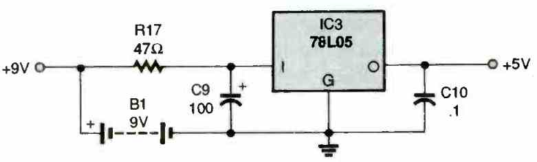
You may have often wondered whether it was feasible to get higher voltages than 12 V from a 7812 IC? In this short post we learn how to configure the […]
Last Updated on July 13, 2021 by Swagatam Leave a Comment
Tone controls are often an important feature of most audio amplifiers, and these are generally available as bass and treble controls, competent at delivering around 12dB approximately of boost or […]
We use cookies for delivering the best experience.Ok
You are here: Home / Mini Projects / Simple FET Circuits and Projects
Last Updated on May 22, 2021 by Swagatam 4 Comments
The Field-Effect Transistor or the FET is a 3 terminal semiconductor device which is used for switching high power DC loads through negligible power inputs.
The FET comes with some unique features such as a high input impedance (in the megohms) and with almost zero loading on a signal source or the attached preceding stage.
The FET exhibits a high level of transconductance (1000 to 12,000 microohms, dependent on the brand and the manufacturer specs) and maximum operating frequency similarly is large (up to 500 MHz for quite a few variants).
I have already discussed the FET working and characteristic in one of my previous articles which you can go through for a detailed review of the device.
In this article we will discuss some interesting and useful application circuits using field effect transistors. All these applications circuits presented below exploit the high input impedance characteristics of the FET for creating extremely accurate, sensitive, an wide range electronic circuits and projects.
Field effect transistors or FETs can be easily applied for making astable multivibrator (AMV) circuits. The output from the AMV from the FET configuration is a square wave which includes an amplitude of almost equal to the power supply voltage, and features a low battery drain. This FET square wave generator circuit can be operated with a battery supply of 9V.
The Drain current consumption is quite low at around 360µA. The waveform exhibits an extremely good symmetry which is normally achieved by matching the FETs through the circuit shown on the left hand side. The FETs must be matched based on their equivalent drain currents. The operating frequency is determined by the values of the resistor R3 and the capacitor C1. The values as shown in the diagram would produce a frequency of approximately 15kHz.
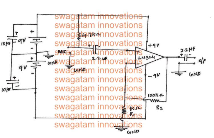
FETs work very nicely for making mini AF amplifiers because it is small, it offers high input impedance, it demands just a tiny amount of DC power, and it offers great frequency response.
FET based AF amplifiers, featuring simple circuits, deliver excellent voltage gain and could be constructed small enough to be accommodated within a mic handle or in an AF test-probe.
These are often introduced into different products between stages in which a transmission boost is required and where prevailing circuitry should not be substantially loaded.
Figure above exhibits the circuit of a single-stage, one-transistor amplifier featuring the many benefits of the FET. The design is a common-source mode which is comparable with and a common-emitter BJT circuit.
The amp's input impedance is around the 1M introduced by resistor R1. The indicated FET is a low-cost and easily available device.
Voltage gain of the amplifier is 10. The optimum input-signal amplitude just before output-signal peak clipping is around 0.7 volt rms, and the equivalent output-voltage amplitude is 7 volt rms. At 100 % working specs, the circuit pulls 0.7 mA through the 12-volt DC supply.
Using a single FET the input-signal voltage, output-signal voltage and DC operating current could vary to some extent across the values provided above.
At frequencies between 100 Hz and 25 kHz, the amplifier response is within 1 dB of the 1000 Hz reference. All resistors can be 1/4 watt type. Capacitors C2 and C4 are 35-volt electrolytic packages, and capacitors C1 and C3 could be just about any standard low-voltage devices.
A standard battery supply or any suitable DC power supply works extremely; the FET amplifier can also be solar driven by a couple of series attached silicon solar modules.
If desirable, constantly adjustable gain control could be implemented by replacing a 1-megohm potentiometer for resistor R1. This circuit would nicely work as a preamplifier or as a main amplifier in a lot of applications demanding a 20 dB signal boost through the entire music range.
The increased input impedance and moderate output impedance will probably meet the majority of specifications. For extremely low-noise applications, the indicated FET could be substituted with standard matching FET.
The next diagram below exhibits the circuit of a two-stage FET amplifier which involves a couple of similar RC-coupled stages, similar what was discussed in the above segment.
This FET circuit is designed to provide a large boost (40 dB) to any modest AF signal, and could be applied both individually or introduced as a stage in equipment requiring this capability.
The input impedance of the 2-stage FET amplifier circuit is around 1 megohm, determined by the input resistor value R1. All round voltage gain of the design is 100, although this number might deviate relatively up or down-with specific FETs.
The highest input-signal amplitude prior to output-signal peak clipping is 70 mV rms which results in the output-signal amplitude of 7 volts rms.
Under full functional mode, the circuit might consume roughly 1.4 mA through the 12-volt DC source, however this current could change a bit depending on the characteristics of specific FETs.
We did not find any need for including a decoupling filter across stages, since this type of filter could cause a reduction in the current of one stage. The unit's frequency response was tested flat within ± 1 dB of the 1 kHz level, from 100 Hz to better than 20 kHz.
Because the input stage extends “wide open,’’ there could be a possibility of hum pick up hum, unless this stage and the input terminals are properly shielded.
In persistent situations, R1 could be decreased to 0.47 Meg. In situations where amplifier needs to create smaller loading of the signal source, R1 could be increased to very large values up to 22 megohms, given the input stage shielded extremely well.
Having said that, resistance above this value might cause the resistance value to become same as the FET junction resistance value.
A Pierce-type crystal oscillator circuit, employing a single field-effect transistor, is shown in the following diagram. A Pierce-type crystal oscillator features the benefit of working without a tuning. It just needs to be attached with a crystal, then powered with a DC supply, to extract an RF output.
The untuned crystal oscillator is applied in transmitters, clock generators, crystal testers receiver front ends, markers, RF signal generators, signal spotters (secondary frequency standards), and several related systems. The FET circuit will show a quick start tendency for crystals that are beter suited for the tuning.
The FET untuned oscillator circuit consumes roughly 2 mA from the 6-volt DC source. With this source voltage, the open-circuit RF Output voltage is around 4% volts rms DC supply voltages as much as 12 volts could be applied, with correspondingly increased RF output.
To find out if the oscillator is functioning, shut switch S1 and hook up an RF voltmeter across the RF Output terminals. In case an RF meter is not accessible, you can use any high-resistance DC voltmeter appropriately shunted through a general-purpose germanium diode.
If the meter needle vibrates will indicate the working of the circuit and the RF emission. A different approach could be, to connect the oscillator with the Antenna and Ground terminals of a CW receiver that could be tuned with the crystal frequency in order to determine the RF oscillations.
To avoid flawed functioning, it is strongly recommended that the Pierce oscillator works with the specified frequency range of the crystal when the crystal is a fundamental-frequency cut.
If overtone crystals are employed, the output will not oscillate at the crystals rated frequency, rather with the lower frequency as decided by the crystal proportions. In order to run the crystal at the rated frequency of an overtone crystal, the oscillator needs to be of the tuned type.
Figure A below indicates the circuit of a basic crystal oscillator designed to function with most varieties of crystals. The circuit is tuned using screwdriver adjustable slug within inductor L1.
This oscillator can be easily customized for applications such as in communications, instrumentation, and control systems. It could even be applied as a flea-powered transmitter, for communications or RC model control.
As soon as the resonant circuit, L1-C1, is tuned to the crystal frequency, the oscillator starts pulling around 2 mA from the 6-volt DC source. The associated open-circuit RF output voltage is around 4 volts rms.
The drain current draw will be reduced with frequencies of 100 kHz compared to on other frequencies, because of the inductor resistance utilized for that frequency.
The next Figure (B) illustrates a list of industrial, slug-tuned inductors (L1) which work extremely well with this FET oscillator circuit.
Inductances are selected for the 100 kHz normal frequency, 5 ham radio bands, and the 27 MHz citizens band; nevertheless, a considerable inductance range is taken care of by manipulation of the slug of each inductor, and a broader frequency range than the bands suggested in the table could be acquired with every single inductor.
The oscillator could be tuned to your crystal frequency simply by turning the slug up/down of the inductor (L1) to get optimum deviation of the connected RF voltmeter across the RF Output terminals.
Another method would be, to tune the L1 with a 0 - 5 DC hooked up at point X: Next, fine-tune the L1 slug until an aggressive dip is seen on meter reading.
The slug tuning facility gives you a precisely-tuned function. In applications in which it becomes essential to tune the oscillator frequently using a resettable calibration, a 100 pF adjustable capacitor should be used instead of C2, and the slug utilized just to fix the maximum frequency of the performance range.
The phase-shift oscillator is actually a easy resistance-capacitance tuned circuit that is liked for its crystal clear output signal (minimum distortion sine wave signal).
The field-effect transistor FET is most favorable for this circuit, because the high input impedance of this FET produces almost no loading of the frequency-determining RC stage.
The figure above exhibits the circuit of a phase-shift AF oscillator working with a solitary FET. In this particular circuit, the frequency depends upon the 3-pin RC phase-shift circuit (C1-C2-C3-R1-R2-R3) which provides the oscillator its specific name.
For the intended 180° phase shift for oscillation, the values of Q1, R and C in the feedback line are appropriately chosen for generating a 60° shift on each individual pin (R1-C1, R2-C2. and R3-C3) between the drain and gate of FET Q1.
For convenience, the capacitances are selected to be equal in value (C1 = C2 = C3) and the resistances are likewise determined with equal values (R1 = R2 = R3).
The frequency of the network frequency (and for that matter the oscillation frequency of the design) in that case will be f = 1/(10.88 RC). where f is in hertz, R in ohms, and C in farads.
With the values presented in the circuit diagram, the frequency as a result is 1021 Hz (for precisely 1000 Hz with the 0.05 uF capacitors, R1, R2. and R3 individually should be 1838 ohms). While playing with a phase-shift oscillator, it might be better to tweak the resistors compared to the capacitors.
For an known capacitance (C), the corresponding resistance (R) to get a desired frequency (f) will be R = 1/(10.88 f C), where R is in ohms, f in hertz, and C in farads.
Therefore, with the 0.05 uF capacitors indicated in figure above, the resistance needed for 400 Hz = 1/(10.88 x 400 X 5 X 10^8 ) = 1/0.0002176 = 4596 ohms. The 2N3823 FET delivers the large transconductance (6500 /umho) necessary for optimum working of the FET phase-shift oscillator circuit.
The circuit pulls around 0.15 mA through the 18-volt DC source, and the open-circuit AF output is around 6.5 volts rms. All resistors used in the circuit are or1/4-watt 5% rated. Capacitors C5 and C6 could be any handy low voltage devices.
Electrolytic capacitor C4 is actually a 25-volt device. To ensure a stable frequency, capacitors Cl, C2, and C3 should be of best high quality and carefully matched up with capacitance.
The next diagram reveals the circuit of a self-quenching form of superregenerative receiver constructed using a 2N3823 VHF field-effect transistor.
Using 4 different coils for L1, the circuit will quickly detect and start receiving the 2, 6, and 10-meter ham band signals and possibly even the 27 MHz spot. The coil details are indicated below:
The frequency range enables the receiver specifically for standard communications as well as for radio model control. All inductors are solitary, 2-terminal packages.
The 27 MHz and 6 and 10-meter inductors are ordinary, slug-tuned units that needs to be installed on two-pin sockets for quick plug-in or replacing (for singleband receivers, these inductors could be soldered permanently over the PCB).
Having said that, the 2-meter coil has to be wound by the user, and also this should be furnished with a push-in type of base socket, apart from in a single-band receiver.
A filter network comprising (RFC1-C5-R3) eliminates the RF ingredient from the receiver output circuit, while an additional filter (R4-C6) attenuates the quench frequency. An appropriate 2.4 uH inductor for the RF filter.
To check the superregenerative circuit in the beginning:
1- Connect high-impedance headsets to AF output slots.
2- Adjust the volume-control pot R5 to its highest output level.
3- Adjust regeneration control pot R2 to its lower most limit.
4- Adjust the tuning capacitor C3 to its highest capacitance level.
5- Press the switch S1.
6- Keep moving the potentiometer R2 until you find a loud hissing sound at one specific point on the pot, which indicates the start superregeneration. The volume of this hiss will be pretty consistent as you adjust the capacitor C3, however it should enhance a bit as R2 is moved up towards the uppermost level.
7-Next Hook up the antenna and the ground connections. If you find the antenna connection ceases hiss, fine-tune the antenna trimmer capacitor C1 until the hiss sound comes back. You will need to adjust this trimmer with an insulated screwdriver, only once to enable the range of all frequency bands.
8- Now, tune in signals in each and every station, observing the AGC activity of the receiver and the audio response of the speech processing.
9-The receiver tuning dial, mounted on C3 could be calibrated using an AM signal generator attached to the antenna and ground terminals.
Plug-in high-impedance earphones or AF voltmeter to AF output terminals, with each tweaking of the generator, adjust C3 for getting optimal level of audio peak.
The upper frequencies in the 10-meter, 6-meter, and 27 MHz bands could be positioned at the identical spot over the C3 calibration by altering the screw slugs within the associated coils, using the signal generator fixed at the matching frequency and having C3 fixed at the required point close to minimal capacitance.
The 2-meter coil, nevertheless, is without a slug and has to be tweaked by squeezing or stretching its winding for alignment with the top-band frequency.
The constructor should keep in mind that the superregenerative receiver is actually an aggressive radiator of RF energy and may severely conflict with other local receivers tuned in to the identical frequency.
The antenna coupling trimmer, C1, helps to provide a little bit of attenuation of this RF radiation and this might also result in a drop in the battery voltage to the minimum value which will nevertheless manage decent sensitivity and audio volume.
A radio-frequency amplifier powered in front of the superregenerator is a extremely productive medium for reducing RF emission.
C1 creates a buffer barrier between the level meter circuit and the audio signal input. VR1 is used for fine tuning the input signal to the gate of the FET, so this pot works like a sensitivity control.
Audio power through the FET drain builds up a voltage around R2, and is connected to the full-wave rectifiers by C3. Current from this bridge rectifier configuration flows by means of the meter, to indicate an equivalent reading that is determined by the power of the fed audio signal.
This form of sensitive level meter or VU meter is advantageous for recording music through a calibrated scale that is supplied through VR1. It can be used likewise used to keep track of the level of audio signals commonly. The loading offered by the network of C1/VR1 is going to be of minimal significance for the majority of medium or reasonably low impedance circuits.
For apparent causes, AF obtained can be from a position right after any gain or volume controls in the sound products. The location where the signal amount is considerably excessive, a resistor could be positioned in series with C1. The value of this resistor relies on the signal voltage, however could be anticipated to lie between around 470k and 10 megohm
The following figure displays the circuit of a symmetrical electronic DC voltmeter featuring an input resistance (which includes the 1-megohm resistor in the shielded probe) of 11 megohms.
The unit consumes roughly 1.3 mA from a integrated 9-volt battery, B, thus could be left operational for long periods of time. This device specializes 0-1000 volts measurement in 8 ranges: 0-0.5, 0-1, 0-5, 0-10, 0-50, 0-100
Hottest Shemale Tube
Joy With Girl Femdom
Sex Pussy Bww
Strapon Anal Orgasm
Granny Fuck Foto
Simple Hobby Electronic Circuit Projects | Homemade ...
Blog
Simple FET Circuits and Projects | Homemade Circuit Projects
Generate HHO Gas Efficiently at Home | Homemade Circuit ...
Grid Dip Meter Circuit | Homemade Circuit Projects
How to Make Dog Barking Preventer Circuit using High ...
100 Homemade Circuit Projects ideas | circuit projects ...
Best Electronic Circuit Projects. Updates by homemade ...
Www Homemade Circuits Com


.jpg.1200x.jpg)