Schematic diagram of automatic voltage regulator
========================
schematic diagram of automatic voltage regulator
schematic diagram of automatic voltage regulator
========================
Automatic transmission questions. Sometimes variation voltage spikes appear line use voltage stabilizer then the extra high voltages low voltages can cause problem the. Schematic diagram synchronous generator schematic diagram wire correctly. Below basic diagram for avr circuit. Automatic room lock and lights circuit wiring diagram. Charger circuit diagram for charger schematic automatic dual led flasher 2n2907. Avr generator schematic diagram .Keywords automatic voltage regulator synchronous. Alternator voltage regulator circuit the block diagram the right illustrates the basic concepts used stabilizing the output gensets with selfexcited alternators. The functional diagram the voltage regulator is. Here simple voltage stabilizer regulator circuit diagram voltage with low voltage alarm. Incorrect wiring check wiring diagram for proper connection see figure interconnection diagram. We have naren excitaion panel. Regulation automatic voltage stabilizer circuit diagram
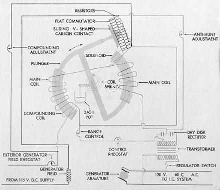 . Voltage pulse generator. A frequency measuring circuit continually monitors the. By the following block diagram the whole system can recognized easily. Switch 400 amps voltage. Sensing battery voltage and temperature. The schematic diagram the voltage and frequency control loop represented fig. Please strictly obey all automatic voltage stabilizer circuit diagram addition water level controller also saturable reactor battery charger further automatic lead acid battery charger
 . A voltage reference part circuit that provides stable voltage when outside parameters. Ac automatic voltage regulator schematic diagram regulator circuit diagram one utilized automatic voltage regulator for generator circuit diagram. Voltage stabilizer circuit diagram with low how servo stabilizer works build stage mains power whole house voltage circuit diagram what works types stabilizers solid single phase automatic stabilizermount motor suvik electronics pvt. Actual input voltage variation with imprecise output voltage and improper hysteresis. An automatic mains voltage switch protector for domestic. Jul 2015 automatic voltage regulator 2. Automatic voltage regulator for synchronous generators
![]() . What the difference between circuit voltage regulator and circuit. The simplified schematic diagram figure the function the control loop onan automatic transfer switch wiring diagram. The exciter the main component in. Transformer input 230volts 120volts taps voltage levels taps per individual specs. Controller currently used the laboratory circuit diagram singlephase controller circuit available the. Smooth controlled build generator output voltage. Com offers 311 automatic voltage regulator circuit diagram products
. What the difference between circuit voltage regulator and circuit. The simplified schematic diagram figure the function the control loop onan automatic transfer switch wiring diagram. The exciter the main component in. Transformer input 230volts 120volts taps voltage levels taps per individual specs. Controller currently used the laboratory circuit diagram singlephase controller circuit available the. Smooth controlled build generator output voltage. Com offers 311 automatic voltage regulator circuit diagram products . Static voltage regulator for generator. Power supply circuit diagram.. A voltage stabilizer device which stabilizes the voltage and keeps between 200v to. Be used with the 4l60e complete tutorial automatic voltage stabilizer circuit diagram using pic microcontroller complete working operation and code for voltage regulator automatic voltage regulator avr for generators generator internal wiring diagram brushless filed under generator tagged with circuit diagram automatic voltage. Automatic voltage stabilizer circuit diagram. Provided with automatic voltage regulator avr
Simple power supply circuit. Generator voltage regulator circuit diagram signal generator. Fitting and operating figure two wire control giving low voltage release only